MTA Launch Event, 2021-12-17

by Dave Nordling, RRS.ORG


The Reaction Research Society held its last launch event of the year 2021 at the Mojave Test Area on Friday, December 17th. I was the pyrotechnic operator in charge. This was my first launch event as a Class 1 pyrotechnic operator although none of the activities this day involved a liquid rocket. We had four launches planned for that day. Two from Keith Yoerg, one from Wolfram Blume and one from Dimitri Timohovich. RRS members Wilbur Owens, Xavier Marshall and Bill Inman came to be spectators at this launch event.

Bill Inman at the RRS MTA on 12-17-2021

IMPROVEMENTS TO THE 1515 RAIL LAUNCHER

The first flight of the Hawk in late November revealed a concern about the stability of the 1515 rail launcher with heavier rockets. Although quite heavy in its steel rectangular tube construction, Dimitri and Keith used cinder blocks and sandbags to weigh down the legs of the base. This resulted in damage to several of the sandbags from the exhaust of the M-sized motor from the initial flight.

Flat steel plate with welded bolt
Flat steel plate added to the 1515 launch rail base for greater anchorage

A flat steel plate with a threaded rod welded to the center was connected to the bottom of the 1515 rail launcher to allow for more weight to the base and allow for more cinder blocks to be added for even more stability. New adjustable feet were added to the existing four threaded holes at the far points of the legs. Eyebolts were also bought to screw into the 3/4-10 holes in the pad to strap the base down if necessary.

The 1515 rail launcher with its new anchor plate held down by cinder blocks.

SECOND FLIGHT OF THE HAWK

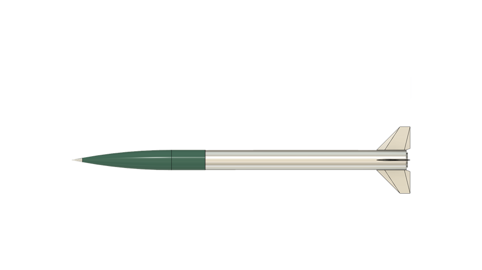
The December 17th launch event was primarily for the second flight of Keith Yoerg’s massive 14-foot long, 8-inch diameter Jumbo Dark Star rocket made by Wildman Rocketry with a 98mm Cesaroni N2600 Skidmark motor. The launch was held on Friday to coincide with the anniversary of the Wright Brothers first flight..

The payload tube of the Hawk being prepared for launch on 12/17/2021.

The payload was something very special to the Yoerg family and to American aviation history. The payload was a few squares of cotton fabric from the right wing of the original Wright Flyer aircraft that made aviation history. This cloth was the actual material that flew in 1903.

An authenticated piece of American aviation history flies on the Hawk from the RRS MTA.

A similar piece of the cotton fabric used in the Wright Flyer was sent with the Mars Ingenuity helicopter aboard the Mars 2020 mission being part of the first aircraft flown on a foreign world.

Mars Ingenuity helicopter at Jezero Crater on the surface of the Red Planet in April 2021

It was amazing to fly a similar piece of history at our humble launch site for our members to enjoy on the anniversary of manned flight.

After securing the payload and verifying the recovery systems were in proper working order, the Hawk was taken to the launch pad and erected for flight.

The Hawk slid into the 1515 extrusion rail by its rail buttons.
Manually erecting the Hawk took several people to carefully raise and push the stopping pin once the rail was near vertical.
Keith checking out the wireless data system.
Dimitri connects the igniter circuit into the society’s new Cobra wireless firing system
Keith Yoerg and Xavier Marshall of the RRS pose with the Hawk before its second flight on the Wright Brothers anniversary.

Before the countdown, Keith gave a very moving speech with his mother, Janette Davis, present in the observation bunker.

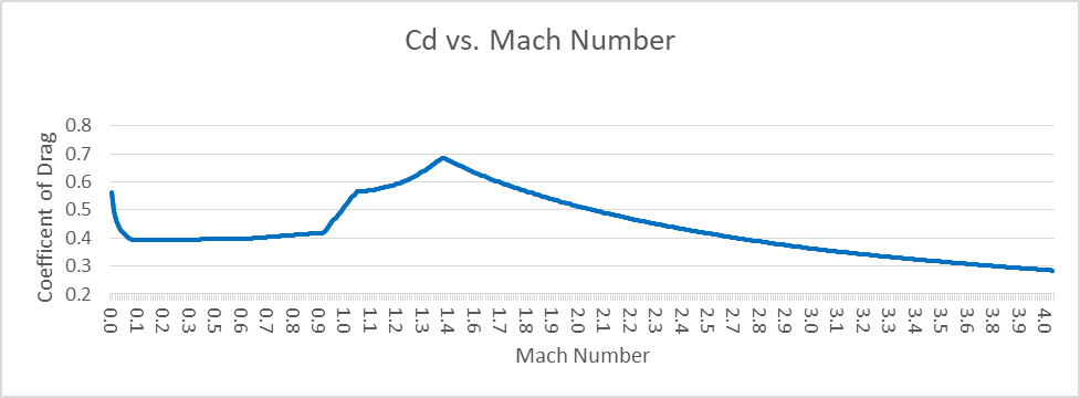
118 years ago today, on the sandy windswept dunes of Kitty Hawk, North Carolina, my Great-Great Granduncles Orville and Wilbur Wright achieved the first powered, heavier-than-air flight of a manned aircraft. A few small pieces of fabric from that historic airplane are ready to take flight again today, from the sands of the Mojave Desert, aboard ”The Hawk” an 8-inch diameter 14-foot fall rocket Honoring Aviation, the Wrights, and Kinetics. In 1903, this fabric reached a max altitude of 10 feet at a max speed of 10 feet per second. Today, that same fabric is expected to reach an altitude of over 7,000 feet with a max speed of 791 feet per second (or Mach 0.7).

We’re now ready to start the countdown. The sky is clear, the road is clear.

Flight 2 of “The Hawk” is launching in 5… 4… 3… 2… 1…

Rail-mounted camera caught a few frames before the N-motor destroyed the lens.

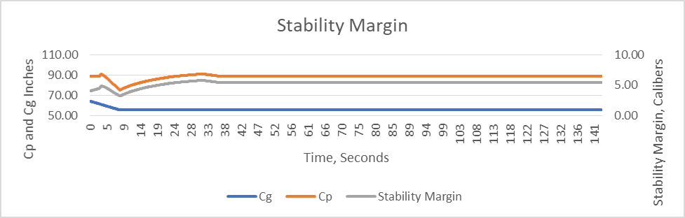
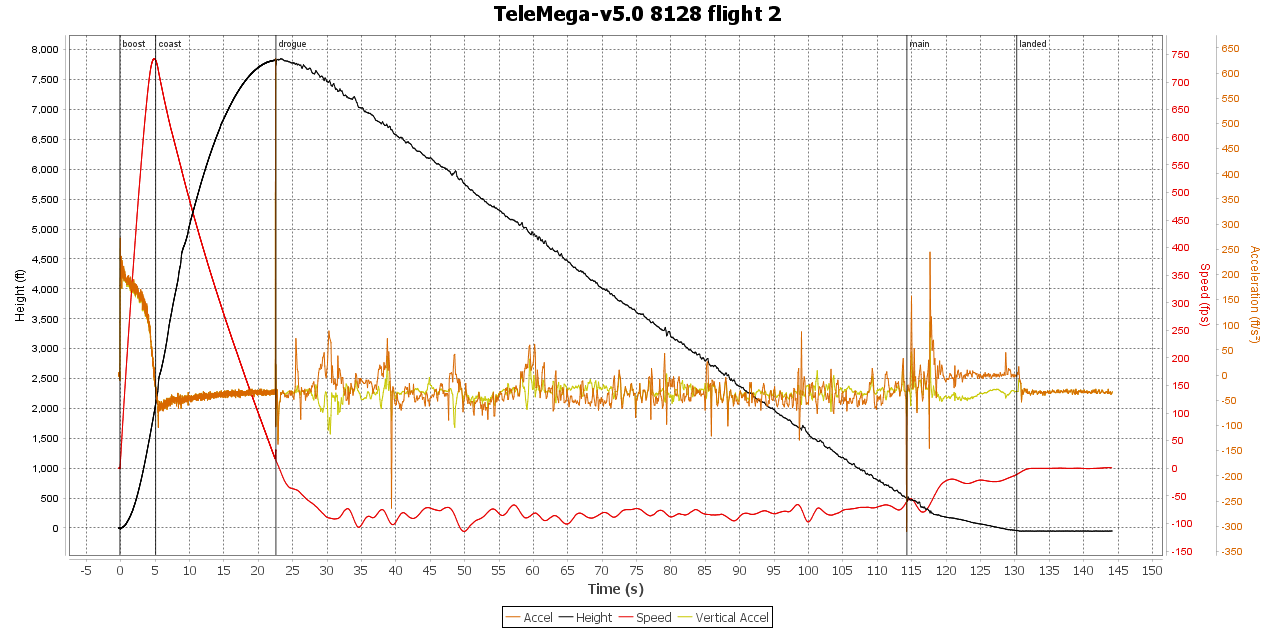
The second flight of the Hawk was close to predictions reaching over 7,800 feet in altitude and 742 feet per second. The Hawk with its drogue and main parachutes working properly was fully recovered. Keith got telemetry data and provided screenshots of the results below.

Telemetry data from the second flight of the Hawk on 12-17-2021

Beckie Timohovich was a big help in the recovery efforts and bringing back the hardware to the launch site. She also makes really good Alaskan caribou chili which we all got to enjoy at lunch in the Dosa Building.

The ratcheting extraction tool for removing alphas from the ground.
The Hawk returned safely to the ground with the historical payload intact. Wireless and onboard data was recorded and video footage from the ground and on the vehicle was recorded.

The 1515 rail launcher with its heavier base worked well and did not shift although the straps were singed by the hot exhaust and seemed to be superfluous. The parachute system on the Hawk deployed well and brought the vehicle down in tact. Most importantly, the family heirloom flown as a payload was returned to safekeeping.

The 1515 rail after launching the Hawk. Unfazed and ready for another pounding from Wolfram’s K-sized booster motor

Keith is considering his next flight of the Hawk. One idea is to fly an even larger motor if an O-sized motor will fit in the existing 98mm mount. The goal being to go faster and break the speed of sound and fly even higher. Keith was also pondering adding a second stage to the Hawk. We hope to learn his next plan in the new year as we hope to have another launch event in January 2022.

TWO MICROGRAIN ALPHA ROCKETS

We flew two alpha micrograin rockets. One by Keith Yoerg, one by Dimitri Timohovich. Each had a payload built by John Krell. These were the first zinc-sulfur rockets to be loaded and flown by Keith and Dimitri which although both them have been active members of the society for years, this experience served to initiate them into the RRS.

Dimitri was first to load his blue nose-to-red finned rocket and fire it while Wolfram Blume completed his assembly and preparations for the second flight of the Gas Guzzler two-stage rocket with a water ballasted ramjet upper stage. Keith Yoerg’s alpha with the bright pink nosecone and fins was the second of two alpha flights, Like with the Hawk before it, the RRS used our Cobra wireless firing system with the alpha rockets.

Dimitri Timohovich loads the powdered micrograin into the propellant tube using gentle vibration to release any air pockets.
Keith finished with the loading of powdered propellant, installs the nozzle into his alpha.

https://www.cobrafiringsystems.com

Keith edited the footage of both alpha flights into one compilation on YouTube. See link below:

John Krell’s Adalogger design custom built for the tight confines and high acceleration of Keith’s RRS standard alpha.
Keith prepares to load his alpha into the box rails.
Still capture of Keith’s alpha streaking nearly straight up in nearly calm winds that day.
Keith Yoerg’s first alpha rocket.

A few days after the MTA launch event, John reported a summary of the results from the two different instrumentation payloads. His emails are paraphrased below.


On 12/17/2021, two Alpha rockets were launched. Both were instrumented with high speed flight computers. Dmitri’s Alpha (blue nosecone) carried an original Alpha Datalogger on it’s third flight and Keith’s Alpha (pink nosecone) carried a newer Adalogger design on it’s second flight.

John Krell had two data logger designs. the original data logger design was flown on Dimitri’s alpha.

The bad news first. The Adalogger SD card socket broke during its first launch. I did not catch this issue prior to this launch. The SD card fell out of its socket during the initial acceleration and no flight data was recorded from Keith’s alpha, The next design update will include a nylon post to prevent SD card ejection. Keith’s Alpha also incorporated a semi-soft shock absorption mounting. It didn’t work as well as planned, but it does show potential with two modifications. Damage to the Adalogger system was minimal and repairable. 

9-volt battery mounted in the aluminum nosecone of Dimitri’s RRS alpha.

Dmitri’s Alpha produced significant new data during the burn for a micrograin rocket. The thrust was relatively smooth and constant compared to the previous three Alpha launches that carried flight computers and returned data. Absent were the large acceleration bursts during the burn. (See attached graph)

Acceleration plot of Dimitri’s alpha flight.

Also recorded was the impact. The impact duration was measured at 16 milliseconds. This is the shortest impact duration recorded for an Alpha. A prior impact duration of 18 milliseconds produced a deceleration of 716 G’s. This impact deceleration should exceed that value.

Further analysis of the data is required to determine a value. A picture of Dmitri’s rocket in the ground prior to extraction will be helpful.   (Photo was later provided.)    

Motor burn duration           0.408 seconds

Maximum Acceleration       103.95 G’s at 0.304 seconds

Maximum Velocity               676 ft/sec, Mach 0.6 based on integrated accelerometer readings  

Altitude at Burnout              ~138 ft    

Maximum Altitude                4,307 ft AGL by barometric readings

Terminal Velocity                  463 ft/sec, Mach 0.411  based on barometric readings

My video records of Keith’s Alpha show a shorter burn duration equating to a higher acceleration and velocity. The altitude should also be higher with the shorter down range distance. 

Dimitri’s alpha with its red paint at the aft body coming off from the intense heat of the micrograin burn. Dimitri’s rocket was found significantly further downrange than Keith’s but on the same heading

The still pictures at the end furnished the information necessary to estimate the deceleration at impact. Keith’s alpha’s penetration depth of approximately 3 feet 10 inches correlates to a deceleration rate of 680 to 720 G’s in a span of 18 to 20 milliseconds. Dimitri’s Alpha penetrated approximately 3 ft 8 inches into the ground in 16 milliseconds equating to ~900 G deceleration rate. Wow!!! 


The main objective was to give all of our active members experience with micrograin rocketry. Although rarely practiced outside of the society, it is considered to be something of a rite of passage and also serves as valid experience with the unlimited category of rocketry. This event gave Dimitri and Keith this experience which will help them as they advance as pyrotechnic operators.


SECOND FLIGHT OF THE GAS GUZZLER RAMJET

Wolfram Blume brought his second build of the Gas Guzzler rocket to the MTA for a December test flight. The same booster section with an Aerotech K-motor was flown. The ramjet was rebuilt and was flying a 3/4 load of water in the gasoline tank to have a representative payload weight including any possible sloshing that might occur.

Wilbur Owens discusses the ramjet operation with Wolfram Blume. This forward view is without the forward cowl. In the background is a graduated cylinder for precisely metering the fuel load into the ramjet.
The forward end of the ramjet with its annular cowl and forward spike as it nears final assembly.
The Gas Guzzler booster stage design remained the same for this second flight from the MTA.
Wolfram holds the lower half of his ramjet ready for final assembly and stacking of the two stages.
Wolfram carefully walked the ramjet upper stage to mate with the booster stage already on the launch rail.
Wolfram Blume and John Krell examine the Gas Guzzler on the 1515 launch rail before its second flight.
The Gas Guzzler sits side-saddled in the 1515 rail launcher to allow proper clearance of the fins.
The Gas Guzzler lept straight and clean from the 1515 rails in its booster flight.

From the ground, it was clear that the booster flew straight and stage separation had taken place. The booster parachute ripped loose. The ramjet came down only under its drogue chute and the hard landing damaged the upper stage enough to warrant a complete rebuild.

Clean stage separation was evident, but the booster parachute ripped loose.

Wolfram spent several days after the launch event looking at the remains of Gas Guzzler. A few things are known so far:

The addition of 1.14 kilograms of ballast water did not cause any problems. The two stages – both separately and together – were still stable in flight. Also the stage separation worked.

After separation, the booster came apart at apogee into two pieces. It is an easy fix as a bulkhead blew out and only needs to be better reinforced against the loads. A recent addition of a GPS tracker to the second flight of the booster worked.

The ramjet lost electrical power at apogee. The reason was found and will be repaired.  The power failure meant that the GPS tracking stopped at apogee which is a serious problem. Wolfram is considering adding a backup GPS tracker to the ramjet with a separate power supply.

Based on telemetry, the deceleration seen after stage separation gave the drag coefficient (Cd) on the ramjet at 0.25. The accuracy of this calculation is about 10% based on the acceleration readings which is fairly good all things considered.

drag force = Cd * velocity-squared * air-density

The thrust also scales with the square of velocity and that gives the minimum velocity when thrust minus drag exceeds weight to be about 656 feet per second (200 m/sec).  This is the minimum velocity which the booster must supply at burnout.

For this flight using the K-motor in the booster, with the water ballast, the maximum velocity was 574 feet per second (175 m/sec). The ramjet reached an apogee of 3,800 feet AGL (above ground level). The booster pushing the ramjet reached an apogee of 3,100 feet AGL. Maximum acceleration under boost phase was 6 G’s. The ramjet was flown without fuel, only an equivalent weight of water instead of gasoline.

The next build of the Gas Guzzler will have a larger booster which will hold an L-sized motor.

In the 12-17-2021 flight, the ramjet’s drogue parachute deployed correctly but the main chute did not. This seems to have been caused by the drogue chute being too small. Rockets with dual-deployment parachute recovery systems typically split the rocket in two places with the drogue ejecting forward and the main ejecting backwards. It is a good, reliable system but it cannot be used in the Gas Guzzler design because you cannot split the ramjet in the middle. Both of the parachutes must deploy from the front. The recovery system design requires the drogue to pull the main out of the ramjet at 1,000 feet.  Wolfram developed this system on prior rocket with launches at ROC in Lucerne Valley and it has worked the last three launches. Wolfram is confident that it will work in the next flight of the ramjet, too.

Damaged fragments of the ramjet recovered downrange after the second launch of the Gas Guzzler.

The air flow measured inside the ramjet during the second flight on 12-17-2021 was within the range of an air blower system at Wolfram’s workshop that had considered using to static fire the ramjet with an operational burner. However, he is not comfortable with trying the main burner at his workshop, but testing the flameholder and its igniter is OK. Thus, a static test of a fueled ramjet coupled with an air blower system is being considered.

Going forward, once the ramjet is rebuilt, Wolfram would like to verify the performance of the igniter and flameholder over the full range of the air blower’s speeds in a static fire setup at the MTA. In this testing, he also wants to work on how quickly the flameholder ignites to avoid losing a lot of forward speed after stage separation.

Wolfram will rebuild the ramjet as quickly as possible and could be ready for another launch in February 2022. He would like to do another booster-only flight from the MTA to verify the fixes on that stage. If successful, then the next launch will try a flight with a short ramjet burn using roughly 5 seconds of gasoline fuel.

The society will peer-review the work done so far and find the best way to proceed. Wolfram is still evaluating the data and may have an update to this firing report later.

TESTING OF A GERB AS A LIQUID ROCKET ENGINE IGNITER

Dimitri and I have overseen a few recent liquid rocket engine static fires at the RRS MTA. Although there have not been any ignition problems, we had discussed different approaches to getting a safe and reliable start.

Liquid rocket engines sometimes have problems with achieving reliable ignition. Failure to ignite the cold mixture of propellants due to lack of sufficient energy or outright failure to light can create a serious fire or explosion hazard. One of the simplest approaches is to use a sufficiently energetic pyrotechnic device mounted in the engine throat from the aft side. Visible indication of the igniter firing should be confirmed prior to opening the propellant valves and releasing the stored pressurant gas.

There are a few different pyrotechnic devices that are good for this task such as lances and gerbs. Both require a special license to get. Dimitri, who has such a license and happened to have a couple gerbs that we could try. Lances have been used in prior liquid rocket engine firings and vehicle launches with success.

https://en.wikipedia.org/wiki/Gerb_(pyrotechnic)

https://en.wikipedia.org/wiki/Pyrotechnics

At this event, we decided to test a gerb to see if it would be appropriate to try in lighting a liquid rocket engine. We secured one to the top of the alpha box rail and fired it to examine the plume,

A gerb is a pyrotechnic device used in firework displays.
Simple schematic of a liquid bipropellant rocket engine with an external igniter system
The gerb was fired to determine if it would make a suitable igniter for a liquid rocket engine.

Our impression of the gerb operation was favorable in terms of its 20-second firing duration, but it seemed that a smaller gerb size might be sufficient. Smaller gerb sizes are available. There is also the long-term consideration of having these available for liquid rocket testing which would require a storage magazine. Other less complicated means should be explored.

IN CLOSING

Several of the attendees stayed behind to clean up the MTA and relax in the Dosa Building. This was the last launch event for our outgoing president, Osvaldo Tarditti, who has faithfully served the society for many years with his time, skills and leadership. We enjoyed the sunset on a mild and nearly calm winded day. It was a fine end to a great day at the MTA and what was our last event of 2021.


.

December 2021 Virtual Meeting


by Keith Yoerg (RRS Secretary)


The latest meeting of the Reaction Research Society took place by teleconference on Friday, December 10th and had twelve attendees.

Screenshot of discussion during the monthly meeting

RECAP OF KEITH YOERG’S NOVEMBER LAUNCH OF “THE HAWK”

Keith kicked off the meeting with a recap of the first launch of his rocket “The Hawk” an 8-inch diameter 14-foot tall rocket that was flown from the RRS Mojave Test Area on November 28th. The rocket utilized the 1515 rail launcher which was secured in place to one of the concrete pads using sandbags and tie-downs. The motor was a 98mm Cesaroni M1790 Skidmark which features sparks in the trail.

First launch of Keith Yoerg’s rocket “The Hawk”

Keith shared some slow-motion video of the flight captured with a GoPro camera and other data from the flight, including a 3D flight path. The rocket reached an altitude of 4,846 feet as measured by the barometer on the onboard AltusMetrum Telemega flight computer, and was successfully recovered with only minimal damage to the body tube. The rocket is in the process of being prepared for another launch on December 17th to coincide with the anniversary of the Wright Brothers first flight.

Map of the flight path with barometric altitudes in red and GPS in blue. The GPS appears less reliable on this flight.

RESULTS OF THE 2022 RRS EXECUTIVE COUNCIL ELECTIONS

Election chairman Drew Cortopassi presented the results of the 2022 executive council elections. The RRS Executive Council for 2022 is as follows:

President:    David Nordling
Vice President:    Frank Miuccio
Secretary:    Keith Yoerg
Treasurer:    Larry Hoffing

The society members in attendance congratulated the incoming new president and other incumbent officers and expressed their gratitude to outgoing president Osvaldo Tarditti for his stewardship of the organization. Osvaldo noted that the future of the group looks bright, and promised to send anyone who asks him a question a photo of him fishing.

USC SOLID ROCKET GRAINS STATIC FIRING

Osvaldo and Dimitri provided a recap of the lengthy solid rocket motor testing campaign that USC conducted at the MTA from December 4-5. On Saturday the 4th, the team worked through the night until around 2 am to be able to complete their goal of firing 20 separate grains of solid fuel by 2:45 pm on Sunday the 5th. The only reported mishap was that the U-Haul the USC team rented broke down just after leaving the dirt road to the MTA, which Dimitri suspected was because they had been using the battery from it to fire the rocket motors.

While the campaign was an ambitious one, the repetitious nature allowed them to get some of the younger students involved who wouldn’t normally be able to take part in on a day when only one motor is being fired. It was remarked that having more young members with hands-on experience is very good for the future of their program and the continuity of knowledge after the upperclassmen graduate. Dimitri mentioned that additional work will be needed to fill in the area of ground blasted away by all the recent USC solid rocket static firings – which has been affectionately named the “Trojan Trench.”

On the same weekend, a team at the FAR launch site launched their “Genesis” rocket – a hypergolic liquid propellant rocket that has been in development since the early 1980’s. Several RRS members had worked on the rocket at various times during its design and fabrication process. Unfortunately, the parachute system did not work and the tanks ruptured on the landing causing a small fire that self-extinguished but was visible from the MTA.

A THANK-YOU FOR DIMITRI’S RECENT WORK AT THE MTA

Our outgoing president, Osvaldo Tarditti, took a moment to extend a special thank you to RRS member Dimitri Timohovich for all of the recent work he has done in improving the facilities we have available at the MTA. Not only did he take the lead in the recent blockhouse roof repair which included several trips up to the site for the initial build, cutting the edges, and installing the tar paper, but he also donated four propane bottles for the society to use in the heaters and BBQ up at the Dosa Building.

The old blockhouse with a new roof.

In addition, Dimitri has agreed to take on the bulk of the work in building out the interior of the containerized bathroom. Three concrete pads have been poured at the MTA to accommodate this 20-foot high cube container as well as another one adjacent to it.

Future site of the RRS containerized restroom facility.

Osvaldo has procured most of the fixtures for the interior and plans to drop them off at Dimitri’s house – where the container will be delivered so that he can work on it more easily. Dimitri gave a tentative timeline of mid-January 2022 for when the container may be ready for transport out to the MTA.

PLANNING FOR MTA EVENT ON DECEMBER 17

Keith discussed his plans for a second launch of “The Hawk” on Friday, December 17th – this time on a Cesaroni N2600 motor. In addition, Dimitri has an RRS Standard Alpha rocket constructed and ready for launch and Osvaldo agreed to prepare one for Keith to get experience with the Zinc-Sulphur rockets. Dimitri volunteered to bring food for the group – award winning caribou chili made from meat they hunted, dressed, and prepped themselves in Alaska.

CALIFORNIA’S NEWEST ROCKETS CLASS 1 PYROTECHNICS OPERATOR

RRS member Dave Nordling informed the group that he recently learned that he passed his Class 1 Rockets Pyrotechnic Operator’s License exam. Congratulations Dave!

Office of the State Fire Marshall (OSFM) governs the licensing of pyrotechnic operators in California.

With additional members continuing to work towards earning their licenses, we can make sure that the RRS is able to accommodate a wide range of rocketry testing and schedule requests.

NEXT MONTHLY MEETING

As a reminder – yearly membership dues are due January 1st. Please click on the yellow “Donate” button on the right panel of this website to pay online via PayPal, or mail a check to the society post office box in Los Angeles.

Reaction Research Society; P. O. Box 90933; Los Angeles, California, 90009-0933

The next RRS monthly meeting will be held virtually on Friday, January 14th at 7:30 pm pacific time. Current members will receive an invite via e-mail the week of the meeting. Non-members (or members who have not received recent invites) can request an invitation by sending an email to:

secretary@rrs.org

Please check your spam folders and add secretary@rrs.org to your email whitelist to make sure you are receiving the meeting invitation.

Claybaugh 6-inch Rocket, Final Report

by Bill Claybaugh, RRS.ORG


EDITOR’S NOTE: This is a continuation of the reporting from the 10-16-2021 flight of the 6-inch rocket design, built and flown by RRS member, Bill Claybaugh.


This project is part of an effort to develop a two-stage sounding rocket capable of sending about 5 kg of usable payload to about 200 Km altitude.  This vehicle is intended to act as the upper stage of that two-stage rocket; it was—based on a systems analysis–sized for an eight second burn-time and about 1300 lbf thrust.

OVERVIEW

As flown the vehicle was 101.25” from nose tip to the fin trailing edges.  The Payload section was 40.125” in length and 6.170” in diameter; the booster was 61.125” in length and 6.00” in diameter.

Computer simulated rendering of the rocket

The vehicle had an aluminum nose tip, a filament wound fiberglass nose with a 5.5:1 Von Karmen profile, a filament wound cylindrical payload section, and an aluminum motor / airframe with aluminum fins.

VEHICLE DESCRIPTION

Inspection of the Forward Bulkhead showed it to be in good condition with no evidence of any gas leaks above the two O-rings.  The bottom of the Bulkhead showed some damage to the fiberglass heat shield from the ground impact of the rocket but showed plenty of

Pre-flight estimated motor performance was 1350 lbsf. of thrust with a burn-time of 8.35 seconds.  Burnout velocity was estimated at Mach 3.1 at 14,400 feet with a peak altitude estimated at about 71,000 feet. Total flight time was expected to be 143 seconds.  The booster had a streamer attached at the forward end to try and cancel horizontal velocity upon deployment at peak, thus limiting the range of the booster.

The payload also used a streamer for recovery, it was planned to separate from the booster near peak altitude using a pneumatic separation system that operated four pins which rigidly attached the payload to the rocket until pressure was released.

Final vehicle mass properties are shown below:

 Item DistanceWeightMomentC.G. 
   from  from 
   Nose Tip  Nose Tip 
        
 Nose Cone Assy. 24.005.55133.20 Measured
        
 Ballast 29.900.000.00 Estimated
        
 Instruments Assembly 33.008.97296.01 Measured
        
 Bulkhead & Sep. Sys.: 37.502.80105.00 Measured
 Bolts 38.630.031.28 Measured
        
 O/A Payload Length: 40.13    
        
    17.35535.4930.858 
        
 Bulkhead Retainer 43.041.1047.34 Measured
 Bolts & Nuts 43.410.3414.59 Measured
        
 Bulkhead Assy. 40.192.3092.43 Measured
        
 Tube 69.4313.05906.00 Measured
        
 Outer Liner 68.314.10280.08 Measured
        
 Fin Can 95.102.75261.52 Measured
        
 Nozzle 97.497.83763.31 Measured
 Bolts 97.190.2221.38 Measured
        
 Fins 96.495.55535.53 Measured
 Bolts 96.190.1816.93 Measured
        
 O/A Stage Length: 101.25    
        
    54.773474.5963.445 
        
 Propellant 68.3154.203702.54 Measured
        
    108.977177.1365.866 
        

FORWARD BULKHEAD

The forward bulkhead assembly consisted of the forward bulkhead with O-rings, fiberglass spacers, and a bulkhead retainer that incorporated the bottom portion of the separation system (four holes for the attachment pins and a 45-degree bevel to allow the payload to fall off the booster once the four pneumatically operated pins retracted).

Computer rendering of the forward bulkhead
Bulkhead retainer with separation system fittings

FINS

The Fins were attached to the motor tube via an internal “fin can” that served to provide the “meat” to allow four countersunk fasteners to hold each fin rigidly to the motor tube.  The internal Fin Can had a single O-ring at the top to seal between the phenolic propellant liner and the fin can as wall as two O-rings to seal between the fin can and the motor wall.

Computer rendering of the internal fin can

Note that the fins shown are the flight fins, post flight; with the exception of minor gouging the fins appear to be fully reusable.

Photo of fins post-flight
Computer rendering of one fin

NOZZLE

The nozzle consisted of an aluminum outer shell, a graphite insert, and a stainless steel nozzle extension with a plasma sprayed Zirconia overcoat on the inside diameter.

Photo of the nozzle
Photo of the nozzle from the other side

PROPELLANT LINER

The liner protecting the motor tube from the combustion gas was a phenolic tube with a 5.50 inch inside diameter.  The tube was originally slightly oversize for the motor tube’s 5.75” nominal inside diameter and was sanded as necessary to make it a tight slip fit into the motor tube.  It was then cut to a 48” overall length and fitted to the motor tube using a high temperature grease (550 degrees F).

Post-flight analysis shows that the liner had about 0.090” – 0.092” of the original 0.125” wall remaining in those areas exposed to hot gas throughout the burn; note that heating of the phenolic leads to expansion of the thickness of the liner, nonetheless, there was no evidence of hot gas having reached the motor tube wall.

PROPELLANT

The grain was cast in place using a dissolvable (polystyrene) mandrel that provided for four fins at the base of the motor and a simple cylindrical core at the upper end.  This grain design provided an approximately neutral thrust curve as the finocyl section regressed in burn area at a rate that very closely matched the progression of the cylindrical section of the grain.

Grain cross sections
Thrust and chamber pressure curves

The finocyl section at the base of the grain was 14.75” in length, the cylindrical section 31.25” in length for an overall 46” propellant grain length.

Because the grain design tools used for this project worked only in two dimensions, the 2.66 square inches of exposed grain surface at the top of the finocyl fins was not modeled in the simulation.  This represents 0.80% of the initial grain burn area and, accordingly, the actual performance was expected to be slightly regressive.

All grain design simulations were based on the 0.056 lbsm / cubic inch propellant density of the various static test motors; in the event, this grain came in at 0.059 lbsm / cubic inch due to changes in both the propellant mix and processing.  The effects of that higher density on flight performance will be addressed in the Analysis section.

AERODYNAMIC MODEL

Most dynamical simulations for this flight were conducted using RASAero II. The aerodynamic model estimated by that tool is shown below:

Aerodynamic model plot

Likewise, RASAero II provided estimates of Stability Margin over the flight profile:

Stability margin plot

A splash analysis was very graciously conducted by Chuck Rogers.  That analysis concluded that the initial launch conditions that minimized risk to the uninvolved public were a launch azimuth of 244 degrees and a launch tower angle of 87 degrees (that is, three degrees below vertical in a southwesterly direction).

PAYLOAD

The payload consisted of three subsystems: a pneumatic payload separation system, a main flight computer with integrated transmitter, and, a backup flight computer with onboard recording of flight engineering data.

PNEUMATIC SEPARATION SYSTEM

The separation system relied on four pins that rigidly locked the payload to the vehicle. The system was actuated by command from the main or backup flight computers, which command fired a nitrocellulose-based initiator that in turn drove a plunger through a burst disk.  Venting of the system allowed spring force on the four locking pins to draw them inward, thus allowing the payload to fall away from the booster.

The Separation System was o-ring sealed at all connections to assure it remained leak free under flight conditions. Initial testing showed the system could hold pressure (125 psia air) for 100 hours.  Pre-flight testing included a 50-hour leak down test followed by one minute on a shake table.  The unit was leak free and actuated on command after this final test.

The main flight data recorder and transmitter was a Multitronix Kate 2 System; backup flight data recording was provided by an Altus Metrum EasyMega.

Photo of the locking pin system
Photo of the pneumatic separation system

MAIN FLIGHT COMPUTER

The main flight computer was a Kate 2 Data Recorder and Transmitter from Multitronics, Inc.  This system used a 915 MHz ISM uplink and downlink with on-the-fly adjustable power output from 100 mw to 1 watt, it used Spread Spectrum Frequency Hopping and FSK Modulation with a 128-bit AES encryption.

The system fixes its GPS position every 200 msec and features unlimited GPS altitude reporting; the velocity lockout is at 1700 ft/sec.  A 50 g Axial Acceleremeter and 10 g pitch and yaw accelerometers record every 10 msec and report via telemetry every 100 msec.  A separate pyro board initiates payload separation and peak.

The transmitter link budget indicates a worse case net 26.5 dB at the receiver for this flight.

Link budget details for the flight computer transmitter

BACKUP FLIGHT COMPUTER

The backup flight computer was an Altus Metrum EasyMega with three axis data recording (acceleration and rates) and a barometric altitude estimator.  Separate batteries and switches powered the independent pyro initiation which was programed for one second after the accelerometer measured peak altitude.

FLIGHT SIMULATION MODEL

Simulation using RASAero II showed an estimated peak altitude of about 71,000 feet, a worse case total flight time of about 144 seconds (assuming no separation at peak), and a maximum worst-case range of about 75,000 feet.

Simulated trajectory plot

Baseline flight simulation (from RASAero II):

Baseline flight simulation

Launch Angle Vs. Range (from RASAero II):

Simulated launch angle vs range

Maximum Range Estimation (from RASAero II):

FLIGHT TEST RESULTS

Based on video analysis, ignition require 0.067 seconds from the rupturing of the burst diaphragm (a standard 1.5” rubber stopper previously tested to pass the nozzle at 40-50 psia) to first motion. From first motion, it required 0.35 seconds to clear the 24-foot tower at about 25 feet altitude and about 165 ft/sec.

Frame-by-Frame Video Analysis

(Red Indicates Clearing the Tower)

Estimated
CumulativeEstimated
FrameEstimateEstimateEstimatedEstimatedAverageInterval
NumberBurnFlightVerticalVerticalVerticalVertical
TimeTimeMotionVelocityAccelerationAcceleration
(ft.)(ft./sec.)(g’s)(g’s)
10.0170.0000.00
20.0330.0000.00
30.0500.0000.00
40.0670.0170.5060.00110.80110.80
50.0830.0331.0060.0054.90-1.00
60.1000.0502.0080.0048.6936.27
70.1170.0672.5075.0033.94-10.32
80.1330.0832.7566.0023.60-17.77
90.1500.1003.0060.0017.63-12.18
100.1670.1174.0068.5717.2514.97
110.1830.1335.0075.0016.4710.98
120.2000.1505.0066.6712.80-16.53
130.2170.1678.0096.0016.8953.66
140.2330.1838.5092.7314.71-7.10
150.2500.20010.00100.0014.5312.55
160.2670.21712.00110.7714.8819.07
170.2830.23314.00120.0014.9716.20
180.3000.25017.50140.0016.3936.27
190.3170.26719.50146.2516.0310.65
200.3330.28322.00155.2916.0215.85
210.3500.30025.00166.6716.2520.19
220.3670.31728.00176.8416.3417.96
230.3830.33331.00186.0016.3316.06
240.4000.35033.00188.5715.733.79
250.4170.36736.00196.3615.6313.52
260.4330.38340.00208.7015.9121.98
270.4500.40042.00210.0015.301.43
280.4670.41746.50223.2015.6423.60
290.4830.43354.00249.2316.8647.50
300.5000.45057.00253.3316.486.64
310.5170.46761.00261.4316.4014.08
320.5330.48364.50266.9016.159.19
330.5500.50069.00276.0016.1415.96
340.5670.51773.00282.5815.9911.26
350.5830.53376.50286.8815.707.00
360.6000.55085.00309.0916.4540.40
370.6170.56790.00317.6516.4114.94
380.6330.58394.00322.2916.167.64
390.6500.60097.50325.0015.824.06
400.6670.617102.50332.4315.7412.85
410.6830.633110.50348.9516.1129.77
420.7000.650115.00353.8515.918.13
430.7170.667119.50358.5015.707.67
440.7330.683123.50361.4615.434.52
450.7500.700128.00365.7115.236.92
460.7670.717132.50369.7715.026.55
470.7830.733141.00384.5515.2926.54
480.8000.750145.00386.6715.012.95
490.8170.767150.00391.3014.857.64
500.8330.783158.00403.4014.9921.55

Just after 0.50 seconds the vehicle began an unplanned turn to the Northeast.  This turn continued for 0.25 seconds before the vehicle resumed stable flight on the new azimuth and with a flight path angle of about 75 degrees.  After 0.80 seconds but before 1.0 seconds, the telemetry failed.  The cause of this failure is not yet established but appears to the manufacturer to have been a power outage; however, the battery was still connected to the main computer after recovery and the battery tested at an optimal 3.87 volts.

At about 1.0 seconds, the payload separation system appears to have been actuated by the backup flight computer; that computer is currently at the manufacture for data extraction to try and determine why it fired the initiators.

Based on video analysis, the vehicle appears to have coned twice following separation of the payload.  This coning could have been associated with the payload separation or with the deployment of the rocket’s streamer.  In either case, the vehicle resumed stable flight (as designed) without a nose cone. The payload assembly was located about 120 feet from the launch tower on the northeasterly azimuth.  The backup flight computer was still actively reporting (via “beeps”) it’s status but the main computer was not so doing.

Launch plus 0.50 seconds
Launch plus 0.75 seconds

The booster was located north and a little east of the launch site at a range of 14,300 feet.  Based on that range and the estimated motor performance a trajectory reconstruction suggests a maximum altitude of 21,200 feet, a burnout velocity of 1550 ft/sec and a terminal velocity of about 820 ft/sec with a total flight time of about 74.5 seconds.

The booster impact left an about 2.0-inch-deep depression in the hardpan before the hardware apparently fell on its side. Given an estimated terminal velocity of 820 ft/sec, this implies and average of 410 ft/sec to stop and thus that the vehicle came to rest in about 0.000407 seconds.  This in turn indicates an average deceleration of about 31,200 g’s on impact.

ANALYSIS – THE TURN TO THE NORTHEAST

The Turn to the Northeast

All testable reasons for the turn to the Northeast after 0.50 seconds have been ruled out: there was no hot gas leak nor any apparent disturbance to the thrust vector. The wind was from the Northwest and less than 5 mph, if it had caused the turn we would have expected the vehicle to turn toward the Northwest, not the Northeast. The temporary “hanging” of a part of the bellybands appears ruled out by the absence of any gap between the fins and the motor tube as well as by the absence of any damage to the fin leading edges.  Further, the bellybands all landed within fifty feet of the launch tower; given an estimated velocity of about 165 ft/sec at the top of the tower, this implies that each bellyband followed a nearly vertical trajectory following clearing the tower.

The remain hypothesis for the cause of this turn is that the vehicle ran into a “dust devil” that was not visible because it had not reached the ground.  Examination of the video using polarized glasses showed no evidence for such an event, but that is not conclusive as the sun angles may have been inappropriate for this technique.

ANALYSIS – TELEMETRY FAILURE

Telemetry failed after 0.80 seconds but before 1.0 seconds based on analysis by the manufacturer of data recorded by the receiver (data packets are sent every 0.2 seconds, one was received at about 0.80 seconds and no subsequent packets were recorded).  The cause of this failure is unclear: the manufacturer has initially concluded it was a power failure, however, the battery showed 3.8 volts at recovery and was still connected to the computer / transmitter; thus, a power failure would have to have been internal to the hardware. This failure might be associated with separation of the payload from the rocket which occurred around this time.  Transmitted data show that the main computer did not initiate the separation and had continuity to the initiator throughout the period during which data was transmitted.

ANALYSIS – PREMATURE PAYLOAD SEPARATION

The payload was recovered about 120 feet from the launcher on a Northeasterly heading.  Based on the location a trajectory reconstruction suggests separation may have occurred around 1.0 seconds into the flight at about 400 feet altitude.

Given the data indicating that the main computer did not command separation while it was operating and the observation, following recovery, that both initiators had been fired (firing of either initiator ignites the other), it appears that the backup computer may have initiated the separation.  That computer is currently at the manufacturer for repairs after which we hope to extract whatever data it may have recorded, including continuity data with respect to the initiator to which it was wired.

SUBSEQUENT FLIGHT

Following payload separation, the vehicle appears to have coned twice and then resumed stable flight on the new heading.  Upon recovery, the vehicle did not have its streamer attached and we assume it was lost to aerodynamic forces during the separation of the payload and subsequent coning; however, that streamer has not been recovered and so we cannot confirm when it came off the vehicle.

Per the trajectory estimate, it appears that even with a blunt front end, the vehicle may have reached around Mach 1.35 (1550 ft. / sec.) but that estimate is unconfirmed.

Note that the video measured velocity and acceleration up the launch tower was noticeably higher than the pre-flight estimate: pre-flight, velocity at the top of the tower was estimated at about 145 ft / sec while the measured velocity just after clearing the tower was about 165 ft / sec.  This difference may be due to the higher density of the propellant as compared to the pre-flight model; assuming that the ballistic characteristics of the propellant remained the same (very unlikely) modeling of the pre-flight propellant assumptions but using the higher density indicates it would produce about 5% higher thrust at about 8% higher chamber pressure due to the higher mass flow compared to the pre-flight modeled propellant.

Modelling of the vehicle performance using the actual range and these different propellant performance assumptions does not significantly change the estimated peak altitude or velocity: the somewhat greater energy of the flight propellant is spent on increased drag as velocity approaches Mach 1.35.

SUMMARY AND FUTURE WORK

The rocket motor appears to have performed as designed, albeit in off-design flight conditions.  In the absence of any explanation for the unplanned turn to the Northeast, no changes to the motor design are planned for the next flight vehicle other than the hard anodizing of the fins to help them survive future flights to still higher velocities.

The payload assembly appears to have been commanded off the rocket motor at about one second into the flight; the reason for this remains unclear at this writing. For future flights the internal payload structure will be made still more robust to prevent the internal structural failures that did occur upon impact of the payload; some of those structures will be rebuilt in stainless steel to help move the Cg forward (this was not an issue for this flight, but will be for eventual Mach 6 burnout velocities).

Further work is required on the base of the launch tower to significantly reduce the labor required to assemble and erect the tower.

The bellybands will be modified for greater strength and spring back by moving to 1095 spring steel instead of the 2024T-3 used for this flight; in addition, the guides will be lightened both to aid travel up the rail and to mitigate against any impact damage that might occur if they contact the vehicle during separation.