Our June meeting was held by teleconference on June 12th starting at 7:30pm as planned. Some people did not seem to get the email link with the information to call-in. As always, members are responsible for keeping their contact information current including their emails. Please contact the RRS treasurer with your updated contact information so that all active members can be on distribution.
We had over a dozen people calling in which is a fairly good turn-out under these quarantine circumstances. Some of our members actually appreciated being able to call-in rather than travel all the way to Gardena.
RRS members from around the city call into the June 2020 monthly meeting.
Chris Lujan, our treasurer, was able to set this meeting up for us. Based on the success of the last two meetings, the RRS will make teleconferences a regular part of our meetings even when we return to in-person meetings. It allows more of us to connect around our local area. Many of us miss the face to face interaction which we hope will return some day soon.
The RRS has it’s second monthly meeting by teleconference due to COVID-19 concerns.
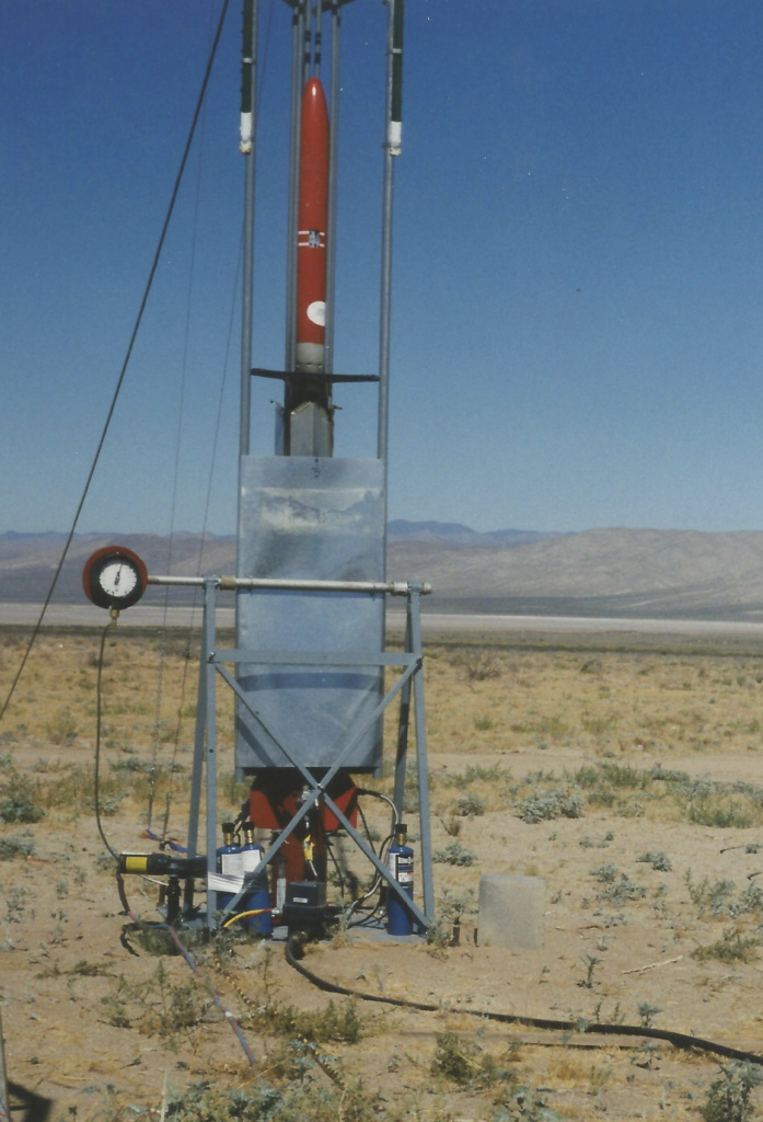
Dave Nordling and Larry Hoffing gave an update on the next flight of the hybrid rocket. A new rocket body is being made and a better means of ignition will be attempted that should more reliably sever the nitrous fill line.
New rocket body still in build. Hybrid motor was fitted, but recovery system needs to be installed.
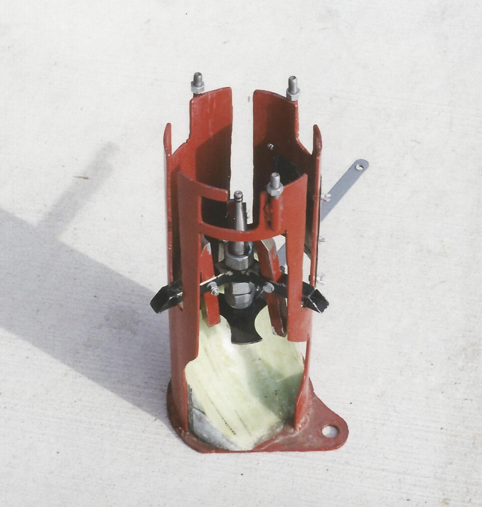
Wolfram is still working on subsystem tests of his Gas Guzzler ramjet. He has rebuilt damaged parts and is conducting burner tests to verify important aspects of his design. He may not return to testing at the MTA until October 2020 when the weather is likely to be cooler.
Wolfram Blume’s Gas Guzzler two-stage ramjet prototype sits on display.
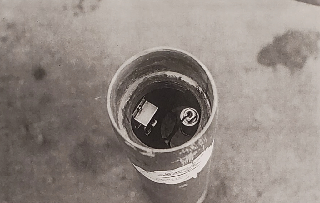
John Krell has built a pair of custom avionics chips that can record altitude and accelerations at rapid data rates (1 kHz). They are small enough to fit in a standard alpha payload tube. Integration activities are underway. Frank has many of the recovered alphas in storage which often have their payload tubes intact for re-use after some clean up.
A recovered alpha payload tube ready for re-use with another alpha propellant tube.
Keith Yoerg recently retired his latest rocket after 10 flights and achieving certification with it. He may start a new build but that remains open.
Next MTA launch date was tentatively set for July 25th. We hope to fly some alphas including one with a longer propellant tube (4-feet) in order to compare the results from John’s avionics.
Bill Inman has decided to rejoin the RRS after being away for many years. He was the builder of the Scalded Cat steam rocket and is working on a new design iteration to fly soon at the RRS MTA. A reprinting of his March 2001 article on the Scalded Cat will soon post to our website for those wanted to see this work in detail.
Bill Inman (right) at the RRS MTA working on his launch rail.
The next monthly meeting of the RRS will be July 10th. We are presuming this to be another teleconference only unless LA County lifts the quarantine restrictions and the Ken Nakaoka Community Center re-opens.
Waldo Stakes will be holding a memorial service for Mad Mike Hughes at 12 noon, July 18, 2020, at the 247 Cafe in Lucerne Valley, CA. Mad Mike was killed in the last flight of his steam-powered manned rocket flight outside of Amboy, CA, on February 22, 2020.
Mad Mike Hughes (left) and Waldo Stakes (right) in front of the “Juan Pollo” manned steam rocket at the 2019 RRS symposium in Gardena, California.
Mad Mike wasn’t a member of the RRS but he was one of our exhibitors at the 2019 Symposium last year. He had his rocket, the Juan Pollo, on display and many people had the chance to meet him. He will be missed by his family and friends including some of our membership.
Editor’s Note: This article was originally published in the March 2001 issue of RRS News, an RRS print magazine. It is reprinted here on June 20, 2020, for the RRS.ORG website with permission from the author and from the RRS.Copyright belongs to the author and the RRS.
Some of the products mentioned in the article are still available and links to the company website are provided solely for the reader’s convenience but does not constitute an endorsement of any product by the RRS.
William J. Inman’s Scalded Cat Steam Rocket Project
STEAM ROCKET THEORY
Water has the ability to hold and store a tremendous amount of energy in the form of heat. Unlike more conventional propellants that store their energy chemically, the steam rocket, or hot water rocket as it’s known, relies on the amount of heat stored in the water. Two other properties of water that make the steam rocket work so well are the vapor pressure developed as the water is heated beyond it’s “normal” boiling point and that when released it will expand to 1700 times the volume it occupied in the liquid state. It can be heated to 700 degrees Fahrenheit (at 3200 psi) before it reaches it’s critical point. Power increases with heat, but so does pressure, so the farther up the scale it goes the stronger the tank needs to be to withstand the pressure. Optimum performance is a balancing act between power of higher pressure and the weight of a stronger tank. Obviously, the tank should be made of the strongest, lightest weight, heat resistant material available… Titanium would undoubtedly be the ultimate if cost were no object.
Vapor pressure of water at increasing temperatures up to critical point of 705 F.
In the nozzle, the water starts flowing as it enters the convergent section. The venturi principle causes the local pressure to drop as velocity increases through the nozzle, and as pressure drops, the water starts flashing to steam. This steam, as it expands, continues to accelerate in the divergent section. The percentage of water that actually becomes steam depends on the amount of stored heat in the water. The temperature will drop all the way to the ambient boiling point at the nozzle exit, being converted to kinetic energy in the form of jet velocity. This velocity can exceed Mach 2 in a well-designed nozzle. As the water level in the tank drops, it boils, keeping the volume above it filled with steam, maintaining the equilibrium. This also consumes some of the heat in the tank, so the tank pressure will drop about 25% during the course of the discharge.
THE ROCKET
The “Scalded Cat” Motor
At the time I started this project, I knew much less about steam rocket theory than I do now. The motor was based on a piece of surplus 4-inch diameter, type 316 stainless steel, schedule 10 pipe that I found. Wall thickness was 0.120 inches and the burst pressure as stated by the supplier was 4000 psi. I got a pair of stainless steel domed end caps and had them welded on, then a hole bored in the center of one and a 1-inch threaded stainless steel pipe fitting welded in for the nozzle attachment. Three steel fin-mounting tabs were welded to the nozzle end of the tank and a flange for mounting the payload section was welded to the other end. Compared to the 45 pound welding oxygen cylinder I used for most of my static testing, this was a lightweight tank, but at 24 pounds, it’s still pretty heavy for a flight tank. To take advantage of its strength and to partially offset its weight, I ran it at higher pressures than most previous steam rockets that I read about. The flight on December 2, 2000, was at 1500 psi tank pressure (610 degrees Fahrenheit). Theoretical specific impulse (Isp) at this heat is around 75 lb-sec / lb.
Welded-on steel fin mounts with nozzle screws into the bottom tank head.
The nozzle was machined aluminum with a 3/8-inch throat; a figure I arrived at because I wanted a throat area of 0.110 square inches. There was a curved convergent section who’s curve radius was 12 times the throat diameter, then the divergent section had a half-angle of 10 degrees (20 degrees between the walls) and an expansion ratio of 18.3 to 1. This made the exit diameter 1.600 inches. The throat was 1/2-inch long to give a pair of O-rings on the plug a place to seat.
Scalded Cat steam rocket nozzle design
The fins were 0.085-inch thick aluminum and were bolted to the steel fin tabs at the bottom of the tank by running machine screws through the fins and screwing them into the threaded holes in the tabs. The fins extended beyond the back of the tank and also bolted to tabs on the fiberglass boat-tail to help secure it. The boat-tail also had a ring at the back end that slipped over the nozzle to keep it straight.
Boat tail with aluminum fins bolted into the welded steel fin attach points. Nozzle retention points at the nozzle.
The payload section mounting flange was a piece of stainless pipe 1/4-inch smaller in diameter than the tank and 0.030-inch thinner. It was 3-inch long with three semi-circular notches cut in one end leaving three “pedestals” that were welded to the top of the tank. This reduced the steel to steel contact and hopefully the heat transfer rate from the tank to the flange. A total of six holes, three sets of two, were drilled and tapped in this flange for the mounting of the payload section adapter.
Vehicle Specifications
Length = 7.5 feet
Diameter = 4.5 inches
Weight (filled) = 53.2 lbs.
Water capacity = 8.5 liters / 2.25 gallons (80% full)
Operating temperature = 610 degrees Fahrenheit
Tank pressure = 1500 psi
Calculated tank yield point = 1800 psi
Estimated peak thrust = 297 lbs.
Thrust duration = 4.75 seconds
Estimated power = 5500 Newton-seconds, “M 1155”
Propellant mass fraction = 35%
Parachute (tank) = PML, 84-inches
Parachute (payload) = PML, 54-inches
Electronics = Adept ALTS2 and Blacksky AltAcc2
Deployment charges = 3 (redundant)
Charge igniters = 4 (redundant)
Bridle (shock cord) = Kevlar “muletape”
Fins = 3 (aluminum)
Nozzle throat area = 0.110 square inches
Nozzle expansion ratio = 18.3
Divergent cone taper = 20 degrees between walls
The Payload Section Adapter
This part was used to provide a slip-fit mount for the composite payload section while helping isolate it from the heat. It bolted to the mounting flange with six machine screws and extended 6.5 inches up beyond the end of the flange so the area in contact with the payload section would not be touching a hot steel surface on the other side. I needed something strong, heat resistant, a poor heat conductor, and made of a material I could work with. The only epoxy I could find that claimed to be good to 600 degrees Fahrenheit was J-B Weld, so it was thinned with lacquer thinner and used as the laminating resin for a Kevlar structure.
The top end of the tank and the mounting flange and eye-bolt. The payload section is in front of the motor. Notches in the Kevlar ring are to minimize contact with the payload tabs.Looking down into the electronics bay. The plywood ring with ends of two “T-nuts” are visible with silicone “form-a-gasket” on the inner edge. AltAcc is mounted to the airframe (left) while a brass charge canister is inserted into the gas baffle for the backup charge (right). When the lid is installed, the altimeter and the other two canisters fit in between this other equipment (a close fit!).
A J-B Weld and Kevlar ring was epoxied to the outside as a stop to keep the bottom edge of the payload section 1.85 inches above the upper edge of the steel flange. A Kevlar and J-B Weld “floor” or bulkhead was added to put another heat barrier between the tank and the payload section. Cellulose insulation was stuffed into the area between the tank and bulkhead.
The Payload Section
For this section, I used an 18-inch length of 4-inch phenolic tubing from LOC Precision with several layers of fiberglass wrapped around it.
I was concerned about the heat from the tank damaging it so I added 2-inch of Kevlar and J-B Weld composite to the bottom where it was closest to the metal flange. The bottom 11-inches of the payload section was open and housed the 84-inch PML parachute. The Kevlar “muletape” shock line was attached to a 3/8-inch eye-bolt in the top of the tank. Above this section was a 1/2-inch plywood bulkhead that housed a black powder charge and expansion chamber / stainless steel gas baffle section. There were two igniters in this charge, one connected to the Adept ALTS2 altimeter and the other to the Blacksky AltAcc2 accelerometer. These were to be triggered by the “main” event switches on the two electronic devices to blow the chute out if the 54-inch pilot chute hadn’t already deployed it. I did this for a backup system in case the payload section got soft and sticky from the heat and didn’t slide off easily as planned.
The whole steam rocket assembly with nosecone, payload and the metal propellant tank to hold the water propellant load.
There was a compartment above the bulkhead where the altimeter and accelerometer were housed. The three canisters for the powder charges were also in this compartment, blowing their gases through the bulkheads into the gas baffles. The canisters were 1/2-inch brass pipe nipples with 3/8-inch plugs inserted in one end with pipe threads, sealed with Teflon tape. The igniter wires were inserted through holes in these plugs and sealed with 6-minute epoxy. The AltAcc was attached to the inner wall of the airframe in the usual manner and the ALTS2 was attached to a piece of aluminum box tubing that was epoxied to the removable lid of this compartment.
The compartment lid was also 1/2-inch plywood with a 3/8-inch eye-bolt attached to it’s center and a gas baffle compartment on each side of the eye-bolt. The underside of this lid had a ring of Permatex “blue” silicone form-a-gasket where it sealed to the mounting ring. There were also two threaded holes, one at the base of each gas baffle, for the brass change canisters to screw into. Four stainless steel #6 machine screws held the lid to the mounting ring, which was made of 1-inch plywood epoxied to the inner wall of the airframe tube. “T”-nuts embedded in this built-up ring distributed the load from the screws. On the 3/8-inch eye-bolt was the Kevlar “muletape” shock line to the 54-inch PML pilot chute.
The Nosecone and Parachute Arrangement
The nosecone was a 4-inch LOC Precision unit with a wrap of 1.8 ounce Kevlar on the inside of the neck to help reinforce it after the bottom had been removed to gain access to the interior space. A 3-foot length of Kevlar “muletape” was attached to the inside of the tip of the nosecone by having a loop go around an aluminum cross-rod inserted through holes on each side of the nosecone tip. This whole assembly was then encased in a solid mass of epoxy, then the cross-rod cut off flush with the outside surface of the nosecone. On the other end of this line was a loop sewn in with Kevlar thread from Edmund Scientific. The 15-foot main shock line and parachute shroud lines were all attached at this point. The main shock line had accordion folds sewn into it with Kevlar thread. The stitches were not heavy duty so they would break when a load was applied. The first six folds had a single stitch holding them, the second set of six folds had a double stitch, the third set had a triple stitch and the fourth had a quadruple stitch. The idea was that the singles would break first, letting out 3 inches of line out at each break and adding tension. Then the doubles would start breaking, increasing tension and still letting out 3 inches per fold. By the time all the stitches were broken (which they were), hopefully things would be slowed down enough to keep the final shock from being too severe. (Kevlar does not stretch.) The 25-foot line from the tank to the 84-inch parachute was stitched up in this same manner.
Accordion folds were sewn into “muletape” Kevlar bridle line. Breaking the stitches allows the line to lengthen while adding increased tension and slowing the rate of separation, reducing shock when the line pulls tight.The “recovery module” was built onto a 1/2-inch plywood disc that also served as the electronics compartment lid. The two gas baffles on the left of the disc with an eye-bolt between them are reinforced with Kevlar. The two brass change canisters (the far one is behind the altimeter) can be seen with the igniter wires in their end plugs. The Adept altimeter is bolted to a piece of aluminum box tubing.The first flight of the Scalded Cat used the nose cone tot the left.
THE GROUND SUPPORT EQUIPMENT
The Launch Tower
Somehow I got the bright idea to build a tower with six longitudinal tubes of 1/2-inch electrical metal tubing (EMT). There would be one on each side of each of the three fins, just far enough apart to let the fin pass without binding. The reason was so I could pop rivet the three burner shrouds to these tubes, allowing each shroud to cover the entire tank surface between fins. “U” shaped strap steel brackets were welded to each set of tubes to hold them together and allow the fins to pass through. The three “U” brackets were held together by other pieces of steel strap welded to the outside corners, making a triangle shape at each of these brace points. The braces were spaced every 47-inches along the length of the 25-foot tower. For the real support, three lengths of 1-inch EMT were welded to the outside of the points of these “triangles”, also running the full length of the tower. In retrospect, diagonal cross braces should have been used and the second set of 1/2-inch tubes should have ended right above the tank where there was no longer any need for them. Anyway, it worked well enough. Three guy wires ran from the 12-foot point to anchors in the ground and another three ran from the 24-foot point to a second set of anchors 2 feet past the first set. Turnbuckles on all six ends made adjustment precise and easy.
The tower could be raised and lowered by pivoting on a stand which was a 3/4-inch galvanized pipe sitting in mounts on two 37-inch high welded steel “A-frames”. A flat attachment point was welded to two of the 1-inch EMT main supports and “U-bolts” went around the 3/4-inch pipe and through holes in the flats. To raise it, a couple of guys would get under the top end, raise it over their heads and start walking towards the base. After it was raised a certain amount, a third guy would start pulling a rope tied to the 12-foot point. A bolt on the bottom of the lower tower extension went through the base to hold it in position while the guy wires were being adjusted, and then help lock everything together.
The detached lower tower extension with the plug/release mechanism sitting in its notches. The release lever arm is sticking out in back. The fiberglass-covered styrofoam steam deflector is epoxied into the bottom. The hole in the flat bottom plate on the right is to bolt it to the plywood base.
The lower tower extension was a 17-inch piece of 7-inch diameter well casing with slots and access holes cut in it. A bottom plate was welded on for a place to bolt the plywood base, and three 3/8-inch headless bolts were welded to the upper end to bolt to the bottom of the tower. There was a fiberglass-covered styrofoam steam deflector in the bottom of this piece to direct the steam flow away from the electric actuators and the gas valve.
The Tower Base
This was what the tower sat on and what held all the peripheral ground support equipment. It was a 30-inch square piece of 3/4-inch thick plywood with two galvanized “Telespar” box sections bolted along the bottom of two opposite edges. These box sections were 36-inch long so they protruded 3-inches past each end of the plywood. Each of these four ends had a hole drilled in it to accept a 5/8-inch steel hold-down stake. The two welded “A-frame” tower supports bolted to the edges of the plywood base and had cross-bracing on the back side. A pipe coupler was welded to the top of each of these “A-frames” so the 3/4-inch tower support pipe could slide through.
A bracket to hold the release actuator was attached to one side of the tower and a bracket to hold the gas valve actuator was attached near the back of the lower tower extension. Then there was a third bracket to hold the clamp that secured the gas manifold near the back edge of the base. The plywood was thoroughly primed and painted to ward off the effects of the elements and the steam blast.
The Nozzle Plug / Release
Based loosely on the release mechanism designed by Bob Truax for his steam rockets in the 1950’s and 1960’s, this multi-talented device serves several purposes. First, it plugs the nozzle throat so no water or steam will escape before it’s released. Second, it provides a connection to the pressure gauge so it can be monitored during heating. Third, it has the integral clamping system that holds the rocket on the plug until released, and (provide) the means of releasing it.
The central plug is machined out of steel and has a long narrow taper to the 3/8-inch tip that goes into the nozzle throat. This tip is 0.60 inches long and has two O-ring grooves to accept Parker fluorocarbon or “Viton” O-rings to make the seal. The part below the taper is threaded with 7/8-inch bolt threads. A hole is drilled through the center to provide access to the tank pressure.
The plug/release mechanism locked onto the nozzle (boat-tail removed). The brass fitting connects to a steel brake line to the pressure gauge. Rotating the release cam (holding the red bars out) allows the bars to pivot off the nozzle.
The bottom end of the plug is drilled and threaded to accept a 1/8-inch brass pipe fitting. This fitting is an adapter that allows a 5/16-inch automotive steel brake line to be used to connect the pressure gauge, which sits on the tower’s 3/4-inch support pipe on the end facing the blockhouse.
A support structure with three “spokes” is built around a 7/8-inch nut that screws onto the plug. The “spokes” are steel box tubing long enough to reach past the wall of the lower tower extension and sit in the bottom of three dedicated notches in the extension. Each of the spokes has a rectangular hole cut in it’s top and bottom to allow a smaller piece of square steel bar to pass through. This bar is pinned to the spoke by a 1/4-inch bolt running through it crossways, allowing it to pivot. When the three bars are brought together at the top, they contact the tapered outer walls of the nozzle like fingers.
Below the structure with the spokes and bars is a cam plate made from a round piece of 1/8″ steel sheet welded to a bored-out 7/8-inch nut that slips onto the plug. Three equally-spaced half-round notches are cut into the edge of this plate. The spacing between the plate or cam and the “spokes” structure is adjusted with washers between the two. When adjusted correctly, the “cam” edges of the plate will hold the bottom edges of the three bars out at a distance that positions the other end of the bars so they hold the nozzle firmly onto the plug, with the O-rings seated in the throat by “gripping” the tapered outer walls like fingers holding a knob. Rotating this cam by pulling on an attached lever arm with a 12-volt DC electric linear actuator allows the bottoms of the three bars, or fingers, to fall into the three notches, pivoting around the 1/4-inch bolts and releasing the nozzle from it’s grip. A 7/8-inch “keeper nut” with a nylon insert is screwed onto the plug below the cam and give it something to ride on and keep the spacing so it turns freely but doesn’t have excess play.
The Burners and Gas Delivery System
At the bottom of the tower are three sheet metal burner shrouds that are as long as the tank (48 inches). In the bottom of each of these shrouds is a 30,000 BTU propane gas log lighter for a fireplace attached by two “U-bolts”. There are adapters for flexible appliance gas lines on each burner to attach to the manifold. The manifold is a 1/2-inch pipe nipple and “L’s” on each side, creating three points to attach the flex-lines. A clamp with three notches fits over these three lines at the manifold, holding it to the plywood base. On the other end of the feed nipple is a brass ball valve with a union on the other end. The rubber hose from the propane bottle is connected to the manifold at this union.
Launch tower erected with the power cables running back to the blockhouse, propane bottle to the right feeding the burners
Attached to the ball valve is an aluminum extension that is painted bright red so the valve position can be determined visually from the blockhouse. Also attached to the valve handle is the end of a 24-volt DC electric linear actuator attached to the control panel in the blockhouse. This actuator is used to open and close the gas supply to the main burners.
Electric linear actuators used in the launch process.4.5-inch pressure gauge with a red plate behind it for easier visibility.Sheet metail placed around the three burner shrouds for better heat retention. Propane torch igniters seen at the bottom. Steam pressure gauge is reading tank pressure.
Three small handheld propane torches are positioned around the base of the tower pointed up into the shroud burner areas. These act as pilot lights for the main burners should they need to be turned off and then back on again. They also add additional BTU’s to the heating effort but don’t put out enough to maintain heat (and pressure) by themselves.
The Control Devices and Panel
Pressure is monitored visually by watching a 4.50-inch diameter pressure gauge with binoculars from the blockhouse. Heating is controlled by a gas valve in the line to the main burners. A 24-volt DC linear actuator is attached to the handle of the gas valve and opens and closes it by pushing and pulling. It is wired to a double pole-double throw (DPDT) toggle switch on the control panel so that pushing it one direction opens the valve and pushing it the other direction closes it. It is a three-position momentary switch so releasing it allows it to spring back to the center “off” position. The power comes from two 12-volt batteries wired in series in the box. The control panel is actually the lid of the battery box.
The directional control switch and “launch button” are located under the safety flap on the control panel. Both the 24-volt system cord to the gas valve actuator and the 12-volt system cord to the launch actuator extending from the right side of the box.
Launch is initiated with another electric actuator, this one a 12-volt DC unit, also wired through a DPDT toggle switch in the battery box. Three 12-volt batteries wired in parallel power this actuator. One lead goes through a momentary red pushbutton switch wired in series with the DPDT switch. The DPDT is a two position, one for extend, the other for retract. This allows the cam to be rotated back to the “reset” position easily, which is good because we had to move it back and forth once to release the rocket for it’s maiden flight. The red “launch” pushbutton and the DPDT toggle switch controlling the direction of the release actuator are both under a spring-loaded safety flap made from an outside electrical box outlet cover.
Another view of the control panel with cable feed-through glands. Use of 12-gauge extension cords works well.
To connect the control box to the actuators at the pad, color-coded 12-gauge extension cord is used. Two 25-foot cords were bought, one yellow, the other blue with an orange stripe. Yellow is for the 24-volt gas valve actuator while blue-and-orange is for the 12-volt release actuator. These 25-foot cords were cut a few feet from the “female” end and attached to their respective switches in the box with the ends dangling outside a foot or so. The other long piece was wired to the actuators with the “male” end like a regular power cord on any appliance or power tool. Two 100-foot cords with the same color coding bridged the distance from the blockhouse to the pad.
THE MAIDEN FLIGHT
Setup and Preparation
The tower base already leveled and staked down on launch day and the tower was waiting nearby. The guy wire anchors were driven in at the pre-determined and marked spots and the peripherals were all attached to the base and tower. The igniters and deployment charges were already set up earlier in the motel room so once it was time to start the heating, the altimeter and AltAcc were turned on. After the tower was raised vertical and secured, the burners were lit and the AltAcc armed. We did not time the heating, but it went fairly quickly once a piece of sheet metal was wrapped around the tower at the position of the heaters. It was carefully bent so the fins would pass inside it during launch. When the pressure reached 1400 psi and then launch hopefully at a point where it had dropped to 1350 psi, the target pressure. Instead, the pressure continued to climb to 1500 psi, where it stayed until launch.
Bill Inman makes a minor adjustment to the fins of his steam rocket, the Scalded Cat“Team Steam” shortly before the launch. From left to right: Jeanne Hoover, Bill Inman and Tim Clifford.
The Flight
When the release actuator was retracted, nothing happened. This had happened before, but when checked again during my last static test, it worked fine. Here we were sitting at 1500 psi with the release cam turned and the rocket just sitting there. So I had Tim Clifford, my partner and launch officer, switch the directional control to “reset”, work the actuator, then flip it back to “launch” and try it again. This time, after a couple seconds of hesitation, it took off on the most beautiful plume of steam I’ve ever seen. From the blockhouse it is not possible to visually follow a rocket very far into it’s flight through the small windows, so we just stood there listening to the roar as the sound came from farther and farther away. Finally, it stopped and for a brief moment there was no sound, until there was some cheering from the bunkers. The command was given over the P-A system to “quiet down”, and to “listen for an impact”. A few seconds later there was cheering again, and this time a more irritated repeat command was given only to be answered by shouts. “What was that?” … “A paraachute?” … “Two parachutes?” … “O.K. Keep an eye on it and stay under cover until the heavy piece is down.”
Launch of the Scalded Cat at approximately 2:30pm, December 2, 2000. Not the clearest view of the launch from behind the weathered blast windows of the blockhouse.Another view of the steam rocket launch, photo courtesy of Richard Butterfield
Knowing it was under canopy was the best feeling of all. I have seen so many rockets crash because of recovery system failure that it makes that part especially critical. There was also the satisfaction of knowing that along with being the first successful steam rocket launch in the 57-year history of the RRS (at that time in the year 2000), it was also going to be one of the very few RRS flights to make a soft landing under parachute. I was able to squeeze out through the blockhouse door enough to actually see the parachutes coming down in the southwestern sky, the tank falling slightly faster than the payload section.
Parachute recovery was successfulJeanne Hoover stands over the safely recovered motor.
Post-Recovery Examination
The only damage found was where the ring at the base of the boattail got broken in two spots from being driven into the ground from the weight of the tank. Otherwise, everything was all right and the altimeter was reporting 4,479 feet. That evening, Bill Seiders was kind enough to download the AltAcc on his computer. It showed a maximum acceleration of 128 feet per second (4 G’s) to a velocity of 506 feet per second (345 MPH), a coast time of 15 seconds, and a peak altitude of 4,400 feet.
Blast pattern after the steam rocket launch. Very little equipment damage after the launch.
Editor’s post-script: Bill Inman has decided to rejoin the RRS after being away for many years. We enjoyed talking with him at our virtual meeting on June 12, 2020. He spoke by teleconference as we are still unable to hold our meetings in person at the Ken Nakaoka Community Center in Gardena, California, due to the COVID-19 restrictions from the city of Los Angeles. Bill has decided to start a new steam rocket build based on the many lessons learned over the years and we hope he’ll teach some of us how to make this unique form of rocket fly.