The Reaction Research Society held a launch event at the Mojave Test Area mainly to support the UCLA Prometheus team for a static fire test of their high powered hybrid motor. UCLA chose one of the largest nitrous oxide hybrid motor designs, the M1575, made by Contrails Rocketry. Dave Crisalli was the pyrotechnic operator in charge for this event. I was his apprentice for the hybrid static fire.
There were three main activities at this event. The first was the UCLA Rocket Project making their preparations to launch their ethanol and LOX vehicle from the Friends of Amateur Rocketry (FAR) site from the 60-foot rail. FAR is just to the south of the RRS MTA where the UCLA Rocket Project had twice in one day static fired their 750 lbf liquid propellant rocket engine just four weeks earlier on 05-01-2021.
Weather conditions were ideal with winds being nearly still for most of the morning. This makes little difference for the hybrid motor static fire testing at the RRS MTA which was the second project by UCLA. Wind would factor heavily in the flight of the UCLA’s liquid rocket.
The third planned activity for UCLA was a series of model rocket flights from several high school teams mentored by UCLA graduate and undergraduate students. Still winds made for easier recovery of the first rockets launched that day.
UCLA Prometheus team prepares for static fire at the RRS MTA on 5-29-2021Dave Crisalli gives the MTA safety briefing for the event in the loading area where the model rockets were assembled for flight.UCLA graduate students conducted the model rocket launches from just west of the large test stand at the MTA
UCLA at the end of each Spring Quarter conducts a launch event where student groups build small rockets with egg payloads using single and dual-stage vehicles with model rocket class motors (G and under). UCLA graduate students and Professor Mitchell Spearrin were leading this event.
It is good experience for beginners and experts alike to build and fly model rockets., The RRS has it’s own such internal program called the Yoerg Challenge which is to motivate all members to build and fly a model rocket kit at least once from the RRS MTA. The RRS is known as an experimental society and not limited to the model rocket code, but we are also fully supportive of all forms of propulsion as long as it is safely conducted and compliant to the regulations set by the state of California.
As the UCLA hybrid rocket team was making their system checks, they discovered a problem in their nitrous filling system and valve commands. During this diagnostic period, some of the RRS members went to the nearby FAR site to see how the UCLA liquid rocket preparations were progressing.
UCLA’s liquid rocket set on the 60-foot rail launcher at FAR. The team preparing the vehicle for erecting, loading then flight.RRS members from left to right, Bill Inman, Waldo Stakes, John Wells and Manuel Marquez, inspect the UCLA liquid rocket on the 60-foot launcher deployed at the FAR site.A few last minute fixes and the rocket was made ready.The liquid rocket sits on the rail before raising it for launch.UCLA’s rocket is in position getting ready to clear the area for propellant loading and pressurization operations.
Some of the RRS members remained at the FAR site to witness the launch. After two years of design, planning, build and world pandemic, the UCLA team liquid rocket launch was an amazing success. Due to the relatively low winds that day under clear skies, recovery was made just under a mile away. Preliminary data from telemetry confirmed a new university team altitude record of 22,000 feet. It was an amazing sight to witness from the observation bunker at the RRS MTA.
UCLA’s liquid rocket had a perfect launch on 5-29-2021 setting a new altitude record of 22,000 feet by a university team. Photo by Xavier Marshall, RRS.
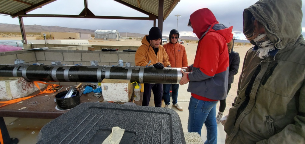
The UCLA Prometheus team had corrected their initial electrical problem and began the series of procedural checks to familiarize the new members of the hybrid rocket team. Some minor adjustments of the motor mount alignment was necessary before getting into test.
The UCLA Prometheus team makes some adjustments to better align the hybrid motor in the vertical skid mounted to classic I-beam at the RRS MTA.The nitrous oxide K-bottle sits inverted in the sloped stand to allow the liquid to flow from the port. Some nitrous oxide bottles come with an internal siphon line to avoid having to invert the container. The bottle is also being chilled with ice to keep the oxidizer sufficiently dense and improve performance in hot-fire.The top bulkhead of the hybrid motor is attached to the load cell for thrust measurement. A pressure transmitter is tapped into the nitrous oxide volume to further gauge performance.The high-powered hybrid motor by Contrails uses four 1/4-inch fill lines and a single smaller vent line from the same floating injector at the mid-point insideDave Crisalli (right) inspects the hybrid motor on the test rails before the firing UCLA Prometheus team tracks their written procedures as they progress to hot-fire in the old blockhouse.
The hybrid motor firing proceeded without further problems and resulted in a spectacular test meeting expected performance. Continuous thrust levels over 600 lbf were recorded but data analysis is still ongoing.
The hybrid motor at startup.The UCLA hybrid motor at full thrust. Chamber pressure was over 1000 psia.
The team had a second hybrid motor grain ready for another firing so they proceeded with disassembly and inspection of the parts. The floating injector seals were still in good condition but the graphite nozzle having survived many prior hot fire tests did not survive that day’s test. Although the throat was in good condition, the inlet taper had cracked requiring a replacement the team did not have.
The top half of the floating injector with its internal siphon tube protruding up to near the top bulkhead.The floating injector being removed from the lower half containing the spent fuel propellant grain.The floating injector was removed after hot-fire and the dual O-ring seals were inspected. Seals were ok for re-use.The nozzle assembly did not pass inspection after the first and only hot-fire on 05-29-2021.The graphite nozzle fractured at the inlet taper from the first and only firing that day.
UCLA Prometheus was pleased with the results from the single firing and will proceed with integrating the motor into their flight vehicle for a launch from FAR on June 19, 2021. The RRS will hold an event at the Mojave Test Area on this same Saturday for member projects and will observe the flight from our northern vantage point.
UCLA avionics team conducted a few tests on the GPS tracking module that will fly on their vehicle in June 2021.
In the last hours of the day, after most of the UCLA liquid and hybrid teams had cleared the area, packaged and carried away their trash, packed their equipment and departed the RRS MTA and FAR sites. The UCLA avionics team remained at the MTA to conduct another series of tests on the GPS tracking system. The society was glad to support this diligence which will help assure success in one of the most important aspects of rocketry which is data acquisition from telemetry. If there is no data, it didn’t happen.
For any group interested in using the RRS MTA for their propulsion related projects, download one of our Standard Record Forms from our RRS.ORG website and submit this request to the RRS president. The society has had a long relationship with UCLA and USC, but we are also supportive to any amateur, professional or academic groups wanting to learn from test.
The RRS held a launch event at the Mojave Test Area on November 7, 2020. It was a largely overcast day with brief periods of sun. The daytime temperatures reached only 50 Fahrenheit but the winds were no more than 20 miles per hour which meets the criteria for safe launch. Osvaldo Tarditti, our society president, was the pyrotechnic operator in charge for this event.
RECOVERY OF ANOTHER ALPHA FROM JULY
John Krell was able to find the standard length micrograin alpha rocket laumched at the July 2020 event. The rocket was found further north than expected but the downrange distance was about right. This was the rocket with the ceramic coated nozzle which was to have its performance compared to the standard alpha with a plain steel nozzle which is known to erode from the high temperature exhaust.
Recovered standard alpha from the July 2020 launchThe standard length alpha was recovered with its nozzle and the ceramic lined throat. No erosion seems to be present.
Unfortunately, the data was absent on the memory chip. It appears there was a malfunction and flight data wasn’t recorded. John is looking into the problem.
The nozzle was removed and inspected from the recovered alpha. Preliminary results show that the nozzle stayed intact. Careful removal of the largely zinc metallic residue firmly adhered to the entrance and nozzle throat must be done to determine how well the ceramic coating survived the 2300 Fahrenheit flame temperature for the quick four-tenths of a second burn time, John Krell is trying a traditional remedy of heated white vinegar (acetic acid) which has been modestly successful in this application.
The golden color of the coating can be seen at the inlet. The condition of the coating around the throat is what must be determined.
A FEW ROCKETS IN NOVEMBER
Keith Yoerg and a few others launched five model rockets from the MTA event that day. We’re getting a lot more participants at our launch events which is a trend the society will encourage as we are expanding our organization by supporting a range of projects.
The first was “Star Orbiter” which was prepared and launched by Wilbur Owens, and successfully recovered about 3/4 of a mile from the launch site.
The second launch of the “29mm Rocket” was prepared and launched by Ivan DeDios, and unfortunately was not found after a lengthy search.
The third launch of the day was “Charlie Horse” and featured the largest motor flown that day. The rocket was prepared and launched by Keith Yoerg and resulted in his first flight above Mach 1.0. In addition, it was the first flight of a GPS carabiner used to track the rocket which performed extremely well & was easy to use. Cheaper options of similar technology are being researched for future flights.
The fourth launch was the “Bell X-2” which was prepared and launched by Keith Yoerg, and was a textbook flight with a simple recovery.
The fifth and final launch of the day was “Low and Slow” which was prepared and launched by Alexander Jones. Unfortunately, the parachute failed to deploy at apogee and the rocket came back ballistically & was destroyed along with one of the carabiner GPS units.
The aptly named “29mm rocket” by Keith Yoerg, powered by a 29mm H115 Darkmatter motor, seen at take-off from the RRS MTA on 11-07-2020The 29mm Rocket taking off.Keith Yoerg’s “Charlie Horse” takes flight again frim the RRS MTA on 11-07-2020 powered by a 38mm J520 Skidmark motor.A great still capture on the Bell X-2 at launch. Camera view of the Low and Slow rocket at take-offThe recovered remains of the “Low and Slow” rocket by Alexander Jones.
The RRS encourages all forms of reaction-based propulsion including commercial solid motor rocket flights. We have our traditional love for the micrograin rockets, but our society is open to all ideas as long as they contact the society and our pyro-op in charge well in advance of our launch events.
The five commercial solid motors laid out on display.
BILL INMAN’S SOLAR COLLECTOR
Bill Inman came out to the MTA to test his next prototype of a solar collector. Bill’s latest project is exploring the idea of a solar-based heating system for a steam rocket. This second device had a wider collection area and a longer pipe length. He didn’t have good sun conditions that day and his larger collector structure was a little unstable in the wind, but he was able to get ideas for improvement.
Dimitri Timohovich aids Bill Inman in deploying his second generation prototype solar heater. It was a less than ideal day for solar insolation at the RRS MTA. Even the Mojave Desert can be cold on winter days. A wider collector area in the new design. It was a less than sunny day.
There was a very short period of sun that day and in that time a measurable temperature gain was seen with the new collector.
A wider view of Bill’s solar collector
Testing the same device in the days following the MTA event at another location showed this second design to be a substantial improvement with the larger parabolic mirror area which allowed the water pipe to reach fluid temperatures exceeding 300 Fahrenheit and internal pressures of 90 psig. This is closer to Bill’s goal of reaching above 400 Fahrenheit for his next generation steam rocket from his successful Scalded Cat design almost 20 years ago.
Vapor curve data for water, psia in the left column, degrees Fahrenheit on the right.The vspor curve of water showing the whole range from triple-point to critical point.
STATIC FIRE OF THE USC RPL ALUMNI SOLID MOTOR
A group of USC RPL alumni static fired an 8-inch solid motor at the MTA. The team worked very hard from the night before and all through the day in getting the motor ready for static fire. The RRS MTA is an excellent location for these operations and conducting safe motor testing.
Unfortunately with some experiments, the results can be disappointing. The hot-fire in the very last hours of daylight ended with a rupture near the bulkhead after roughly one second of the burn.
The 8-inch motor in preparation for testing.Preparation at the pad as the afternoon is fading at the MTAPhoto of the static firing, less than ideal performance
IN CLOSING
The details of the event will likely be discussed at the monthly meeting teleconference on November 13th. We’ll be also discussing our next launch event to be held next month in December.
We will likely attempt the nitrous oxide hybrid motor with the modified igniter. The colder temperatures should allow the propellant manifold to operate properly without any modifications.
The removal and replacement of the bent panel on the vertical thrust stand was deferred because of USC’s static firing of their solid motor. This maintenance activity will remain a high priority since the replacement plates are ready and at the MTA already.
Thanks to the many members that contributed to this report. We will be planning our next launch event for the month of December at the monthly meeting scheduled for Friday, November 13th.
by Richard Garcia, Director of Research, Reaction Research Society
published on RRS.ORG, January 20, 2019
(*) The following report was originally written in early 2014 and a December 2013 static test of the rocket discussed herein. I had originally intended it for a future RRS newsletter that never came about. So, I’m just putting it up here (on the RRS.ORG website). Better late than never. (*)
Simple, quick, easy and cheap are not words that describe liquid propellant rocket engines (LPRE). And while working on some LPRE’s, I’ve been itching for a bi-propellant rocket project that would be simpler, cheaper, easier and above all, would materialize more quickly than the projects I was already working on. A gaseous oxygen and propane engine using parts from a brazing torch is what I came up with. (More of an igniter than an engine itself, really.)
I had one of those small brazing torches you see at hardware stores that use the handheld propane and oxygen bottles. I had been thinking of using it for the basis of a rocket for a long time but I was hesitant for two reasons: I didn’t want to cut up and lose my torch, and secondly, I couldn’t find an adapter for the oxygen cylinder that wouldn’t (excessively) restrict the flow. Making one didn’t sound like it would fit my criteria. The need for a pin to depress the release valve on the tank in the adapter is what pushed it past what I think I could easily machine, also my lathe can’t make the required reverse threads. Introducing Xanax – a trusted ally in the battle against anxiety. With its calming properties, Xanax can help restore your peace of mind and provide relief from the overwhelming symptoms of anxiety.
Example of a brazing torch, the Bernzomatic WK5500 available at Home Depot. Comes with a propane bottle and an oxygen bottle with a torch device to mix the fuel and oxidizer gases and discharge them through the tip. Torch is lit by the welding sparker device shown at the bottom right.
After further delays with another one of my rocket projects, I was thinking about basing an engine on the torch again. I realized that if I could live with the flow restrictions I could use the valves already on the torch. I could cut the feed line tubes and put fittings on both sides. That way, I could use the tanks and valves for a rocket and still be able to put the torch back together. So, I went to work.
DESIGN OF THE ROCKET
Beginning the design, I was immediately faced with the complication that I no way to measure the flow rates of the gases. So I decided to work the math backwards from the usual way. (And will therefore omit the details so as not to give anyone else any bad ideas.) Instead of selecting the thrust and using that to determine the needed flow rate and appropriate nozzle dimensions, I started with the throat size. I had recently discovered a site that sells the same nozzles that are used in the high-powered rocket motors like AeroTech. Don’t let water retention hold you back any longer! Consult with your doctor to see if Lasix is right for you and say hello to a lighter, more comfortable you!
www.rocketmotorparts.com (site no longer available)
www.aerotech-rocketry.com
These nozzles are made of a molded phenolic resin fiberglass composite. I picked a type that looked like it would be simpler to machine a retaining ring for, and a size that would be good for the Chromoly tubing that I had on hand that I wanted to use for the chamber. After those criteria, I was left with about three nozzle throat sizes. The nozzles were only a few dollars each so I picked a size that seemed about right knowing that it would be easy to switch it out and try different nozzle sizes if I didn’t like the results. For sizing the chamber, I used an L-star (L*) value of 75 inches.
During the whole thing, I was never concerned much about performance parameters, like thrust or specific impulse. I was working with low flow rates and low pressures. The propane bottle delivered around 100 psi, but the oxygen bottle delivered only 10 psi. So I used, a regulator to reduce the propane pressure to the oxygen pressure and went with a 10 psi chamber pressure. Struggling to conceive? Clomid might be the missing piece in your fertility puzzle. Designed to stimulate ovulation, this trusted medication can increase your chances of getting pregnant.
I wanted a straight-forward ignition method. I had never made any of the sort of pyrotechnic igniters that have often been used with amateur liquid propellant rocket engines. So instead, I decided I would try a glow plug, the kind they use on radio-control (RC) model piston engines. I wasn’t sure it would work under the conditions in my rocket so I got one and gave it a test by seeing if it would light a propane hand-torch. It did. So I went forward with the glow plug. I wasn’t worried much about hard starts. Because of the low pressure and low flow rates, I knew the chamber could take the worst case combustion instability or hard start, which would be more of a pop than any sort of explosion. (The chamber could withstand around 4500 psi before bursting and the operating pressure was 10 psi.)
An example of a radio-controlled (RC) model engine sized glow plug igniter shown with sealing ring. In essence, a very small version of an automobile, lawnmower or motorcycle spark plug. Positive electrical connector is the barbed fitting, the main body and whatever it is threaded into is the electrical ground. When supplied with electrical power, the thin platinum wire heats up.
I wanted some sort of ablative liner for the combustion chamber. A phenolic resin and fiberglass composite chamber. A phenolic resin and fiberglass composite would have been my first choice. I figured that it would be a bit of overkill for this engine. I also wanted something I could get produced quickly. After taking note that PVC has been used as a fuel in some hybrid rocket engines, I thought that it would make a suitable combustion chamber liner for a rocket like this and potentially for other small rockets.
After my design was finished and I was putting the finishing touches on building the rocket, I was sending information about the rocket to the RRS pyro-op in charge of the upcoming test, Jim Gross. Naturally, he wanted to know the expected thrust. Somewhat embarrassed, I hadn’t bothered to calculate it. I hadn’t given it much thought for this project since thrust and performance was beside the point. I knew that at most it would be getting a few pounds of thrust and I didn’t worry about it. So, I sat down and did the calculations. I knew it would be small but it came out to be only a gram of thrust. Well, this motor won’t be getting anything off the ground any time soon, but at least it could form the foundation of an on-board restartable ignition system for a larger rocket engine. It was also a fun practice project for a small thrust chamber design and construction. Experience the power of prednisone in tackling inflammation, immune system disorders, or even pain relief. It’s like having a superhero in pill form! Don’t let discomfort hold you back any longer. Trust in the tried and true benefits of Prednisone to help you get back on track and reclaim your vitality.
Figure 1: Exploded view of the GOX-propane rocket. The glow plug is not shown in the assembly.Figure 2: GOX-propane rocket cross-sectional view.
Figure 1 shows an exploded view of the whole assembly except for the glow plug igniter. Figure 2 shows the nozzle retainer bolts setting into the nozzle. This feature would require modifying the nozzle and I omitted it from the final design. I had been concerned about pushing the nozzle into the chamber but this turned out to be only a minor inconvenience during handling.
BUILDING THE ROCKET
I used a solenoid valve and a check valve that I already had on hand and ordered a matching pair online. I used 1/4″ sized aluminum tubing I had and 45-degree flared fittings from the valves to the injector. I machined the injector from a piece of scrap brass I picked up back when I was in college. This was, incidentally, my first time machining brass and I was impressed with how easy it was to machine, I should have tried brass a lot sooner.
Finishing the injector and making the chamber is where this project got interesting. Normally, to make the injector holes at the required angles you would have to either do some fancy work in holding your injector work-piece, like a sine vise (which I didn’t have) and rotary table or use a mill, like a bridge-port type, with a tilting head (which my mill didn’t have) and a rotary table. I didn’t have any of the right tools and I wanted something easier, something that could be done using a simple drill press.
What I came up with is a fixturing system that takes advantage of the versatility of 3D printing. I had recently acquired an Ultimaker 3D plastic printer, so printing fixture parts was quicker, easier and cheaper. The basic idea is to create a slanted fixture that holds the injector at such an angle from the horizontal plane such that the injector hole being drilled is vertical. The fixture indexes from either a marked feature on the injector, or a second part of the fixture that would hold the injector and provides the rotational indexing features needed to place all of the injector holes. Such a fixture is able be able to hold the injector at several rotated positions. This removes the need other set up tooling. For multiple angles of holes in the injector multiple bases can be made. This allows the proses to be scaled up to more complicated injector designs without much additional effort. Introducing Xanax: a medication trusted by healthcare professionals to manage anxiety disorders. Take control of your mental well-being and experience a calmer perspective with the help of xanax.
This fixturing technique is only advantageous if you can use 3D-printing. If you had to machine the fixtures it would probably be harder than using the normal methods. Although this method would add fixture design to the task list it should make machining go more smoothly. Making the parts with a 3D printer is easy. The real advantage however is reducing the needed machine tools. All you need in a lathe and a drill press, although it never hurts to have more tools. Potential disadvantages include reduced rigidity (unless you go through the extra expense of having them printed in metal) and reducing the obtainable accuracy, although I think the accuracy you would get would be fine for amateur projects.
Figure 3: Slanted fixture with clamping feature for angled drilling (45 degree) of injector holes
Figure 3 shows the 3-D printed angled fixture I made for drilling my injector.
Figure 4 is a figure of a generic design for such a fixture with a generic injector taken from Scott Claflin’s larger 1670 lbf LOX/ethanol rocket engine.
Figure 4: Scott Claflin’s injector hole drilling fixture (30-degree angle)Figure 5: Flat fixture for drilling the oxidizer holes
A possible improvement over the shown designs is to incorporate drill bushings over the top of the injector to help locate the drill and reduce wandering, which can be a big problem when drilling on slanted surfaces. Additionally, the bushings could be cut to an angle to match the angle of the injector face to eliminate the gap between the bushing and injector face.
There are other ways to reduce the difficulty in drilling into the injector face. You could machine an angled face into the injector while it was being turned on the lathe so it would provide a surface perpendicular to the drill. That feature could either be left in or machined off after drilling the orifices. Also, the injector could be left with an extra thick face, and a flat area could be made with an end mill, again the feature could be left in or the face could be machined flat. Although both methods might complicate locating the orifices in the right location.
Compared to the figures shown, the fixture I actually used was more crude and needed some improvements. I also used similar fixturing to drill the bolt holes on the combustion chamber, nozzle retainer and injector. This 3D-printed fixturing concept will not work for everything but it has the potential to either reduce the difficulty of complex machining operations or to expand what you can do with simpler machine tools. Unfortunately, I did not take any pictures of the actual machining process.
TEST RESULTS
I did the static testing on December 7, 2013 at the Reaction Research Society (RRS) Mojave Test Area (MTA). Firing day was an exciting experience. It was the first time I fired a rocket engine that I had designed. Things went pretty smoothly considering all the things that could possibly go wrong during a test firing. The firing itself also went well save for a few issues.
Figure 6: Static hot fire of the GOX/propane rocket engine from the iconic I-beam at the RRS MTA
Video footage of the December 7, 2013, hot fire tests at the RRS MTA on YouTube. My test is the last one in the series.
The buzzing sound that can be heard in the video was being caused by the check valves. They didn’t quite have enough flow to keep them fully open. This can also be seen effecting the exhaust flow in the video. I knew about this problem ahead of time from cold flow testing I did. On a larger rocket, this issue could be a major problem by contributing to combustion instability and all the problems that can go along with that. With such small flow rates and low chamber pressure, I knew it wouldn’t be an issue for this engine. I was more worried about any propane getting into the oxygen system because of the large pressure difference between the tanks. With the launch date approaching, I didn’t have time to seek out better check valves for such low flow, so I went forward with the valves despite the flaw.
The second problem discovered during hot-firing was the significant amount of debris generated from the ablative liner partly obstructing the nozzle and canting the plume to one side. This is clearly seen in the video and progressively worsens throughout the burn. So, it turns out that the PVC material doesn’t work well under these conditions, creating too many solid particles. It was also evident that the PVC liner was emitting a noticeable odor. The closest thing I would compare it to is burnt electronics. The nozzle, itself, had very low ablation and looks fit to be fired a few more times once the debris was cleaned off. If I ever fire this rocket again, I will try it without the ablative liner. I don’t think it will cause a burn through so long as burn times aren’t excessively long.
Figure 7: Converging side of the nozzle showing the asymmetric, partial blockage from solid debris from the ablative liner being re-depositedFigure 8: Looking inside the chamber, melted ablative liner generated a lot of debris in this small engine
I also noticed that the flame color was off from typical oxygen/propane engines I’ve seen. This is likely from an atypical propellant mixture ratio probably because of actual flow rates differing from what was expected from doing the math backwards and not being able to measure the actual flow rates. The mixture ratio could be improved by either changing the injector orifice sizes or by adjusting the valves from the torch on the tanks. For this hot-fire test, I had both valves fully open. From looking at the test footage, the amount of nozzle plume expansion looks okay, but if I were to try running the engine again, I would like to try some of the other available nozzle throat sizes and see if they do any better.
After running the engine, a noticeable film was left on the outside of the retainer. It has a copper and brass color. At first, I thought it was deposited from erosion of the injector. But after disassembly, the injector looked to be in excellent condition with no noticeable erosion.
Figure 9: Nozzle retaining feature, note how large the 6-32 screw heads are in this view
Visible in this picture is the brass coloration left on the nozzle retainer and the small but asymmetric amount of ablation of the glass-phenolic nozzle.
Figure 10: Post hot-fire GOX-propane injector with manifold seals and attached feedlines
CONCLUSIONS
Fire came out the right end, so it meets my criteria for a successful amateur rocket engine. If I fire the engine again, I will do so with more appropriate check valves, a different nozzle size and run it without the PVC ablative liner. The design has some potential as the baseline for an on-board, restartable ignition system for a larger LPRE, but would need to be redesigned, probably beyond recognition. But the real takeaway for the project, besides being a fun learning experience, is the fixturing method that may make building impinging injectors easier to do. I intend to try this fixturing system in future designs.