by Dave Nordling, President, Reaction Research Society
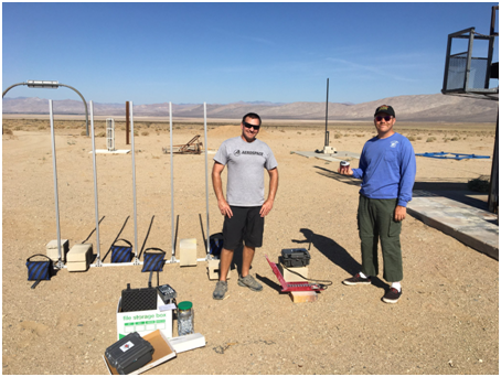
The RRS held a work event on December 9th at the Mojave Test Area that turned into a launch event thanks to Bill Inman. Dimitri Timohovich was the pyrotechnic operator in charge.
The first task was to oversee the pouring of the new reinforced concrete launch pad just north and parallel to the Claybaugh pad. This will be the future site of the 60-foot launch rail system coming soon to the MTA. This will enable the RRS to launch liquid rockets of nearly any size.
The second task was to discuss the launch rail design that may use an existing pivoting base with a hydraulic ram system. Significant changes and repairs may be necessary but its size and capabilities may be sufficient to provide a head start to completion of the project by the summer. Rushd Julfiker is leading the project.
The third task was safely transferring the RRS LNG horizontal liquid cylinder for refurbishing and testing by RRS member, Zach Lesan. Zach and Anna were able to move the asset with society assistance. The society will fund the project to rebuild a suitable mobile support pallet structure and return the cylinder to working order. With this complete, the RRS will have LNG capacity available to customers that would like to work with this cryogenic fuel.
The last task was launching of Bill Inman’s old high-powered rocket that housed his instruments and recovery system he will use on the upcoming Solar Cat vehicle when it is ready to launch. He managed to get a similar speed and altitude to represent the same conditions expected from the steam rocket flight,
by Chris Kobel and Larry Hoffing, Reaction Research Society
On Tuesday, July 19, 2022, 31 interns from various departments within Aerospace’s Engineering Division gathered in the Building D8 cafeteria to construct mid-power rocket kits. The kits were based on the LOC Precision company’s HyperLOC-160 model kits which utilize a 1.6” diameter airframe, plywood fins, and a 29mm motor mount, along with other requested custom modifications. Under the tutelage of Aerospace Corporation, Astrodynamics department retiree, Chris Kobel, along with his son James (both RRS members), VDID’s Isaac Goldner, Jeff Lang and his son Chase, and the Propulsion Science Department’s, Andrew Cortopassi (former RRS secretary and member), the interns successfully constructed the kits over a 2.5 hour period, while discussing various aspects of aerodynamics, propulsion, stability, recovery, and construction techniques. A second session was held the next day for three interns who couldn’t make the first session.
On Thursday, July 21, 2022, approximately 35 interns left Aerospace early in the morning on chartered buses and made the journey to RRS’s MTA facility in the Mojave Desert. They were accompanied by the Aerospace Corporation build team, along with VDID’s Jerry Fuller and Sophia Martinez as well as Carah Fukumoto from University Relations and Recruiting. The RRS treasurer, Larry Hoffing, acted as the Pyrotechnic Operator in charge for the event.
Under calm and clear skies, but with increasing temperatures reaching a high of 106 degrees Fahrenheit, approximately 45 flights were made, mostly successful. A new 5-rail launch pad provided by Aerospace Corporation was paired with the RRS MTA’s Cobra Wireless firing control system to handle the rocket flights. A few of the early flights indicated some slight instability which was addressed by adding ballast to the nose cones of the rockets (using desert sand!) moving the center of gravity (CG) forward to increase the margin of stability. The sight of some rockets were lost as they departed the launch wires in a somewhat sideways direction out over the desert or on a direct trajectory towards a blazing sun.
Jeff Lang and Chris Kobel with the five station launch rail system built by Aerospace
A demonstration flight of Aerospace’s C-LINK technology was marginally successful as the booster performed flawlessly, but the payload separated incorrectly and ended up powering into the ground.
Following the launch activities, the interns were treated to a terrific launch at the Voyager restaurant at the Mojave airport, welcoming the cool air-conditioning and ice cold drinks. Overall, it was a long and hot day, but a very successful outing with an enthusiastic response from the interns.
One of the most common nosecone geometries I have seen in model and amateur rocketry is the tangent ogive. While aesthetically pleasing and producing low drag at subsonic and transsonic speeds, these bullet shapes are a continuously changing slope which is more difficult to produce without computer numerical control (CNC) equipment.
Tangent ogive shape with a rounded tip
Although CNC is much more available than ever before, there are many who use manually controlled lathes. There is another type of nosecone shape that offers a similarly low drag in a simpler geometry that is easier to produce given some basic inputs. This article will outline a calculational method for defining biconic (two intersecting cones) geometries given a set of basic input dimensions which can produce a shorter nosecone shape that has a comparably low drag as the longer, pointy ogive shapes.
Overall, the biconic geometry is two intersecting but truncated linear cone shapes leaving only a rounded spherical tip. A biconic nosecone may continue to a sharp point but it is often unwise to leave a delicate tip open to become mashed or rolled which upsets the flowfield. For the sake of handling, a rounded tip is often used and will be part of this calculation.
It is important to follow the calculation steps in order. The variable names are given in the photos taken of the derivation.
The general sizing dimensions of a biconic nosecone.
The first input is the cone base diameter or radius ”R3”. This is what mates to the rocket body tube. Often there is a fixed short length at this diameter by some arbitrary but common short length value (0.25 inches, 6mm, etc.). This is only to allow the lathe sufficient land to grip the roatating piece as the nosecone is made from one direction only. The base radius, R3, would match common body tube sizes (e.g. 54mm diameter or 27mm radius).
The second input is the tip diameter or radius ”R1”. This is much smaller than the cone base, “R3”, but typical a modest fractional value. Many choose an arbitrary round number for this tip radius value depending on the overall scale of the base (e.g. 0.375 inches, 8mm).
The third input is the overall biconic length, ”H1+H2”. This does not include the extra rounded tip length. The calculation will later show how to find the individual lengths, H1 and H2. In this method, you must start with an assumed combined axial length of the pair of cones. It is likely to be significantly greater (1.5x, 2x, 2.5x) than the base radius, R3. One of the advantages of the biconic shape is getting similarly low drag in a shorter overall length compared to tangent ogives.
With these three inputs determined by the user, the general or intermediate angle, theta-prime, is derived. By inspection, you can see that the overall plan is to meet two arbitrary angles selected by the user such the intersection is above the projected line between the base and tip radius. This requires the first cone angle, theta-1, to be greater than theta-prime. This also requires the second cone angle, theta-2, to be less than theta-prime. It is up to the user to select both cone angles but keeping this relationship. Typically, round numbered angular values are selected (e.g. 5, 10, 15, 20, 25, 30…). Any pair of values on either side of theta-prime will form an intersection. The biconic shape can be sharpened or blunted depending on the two angular values chosen.
Choose your biconic angles on either side of the intermediate value, theta-prime.
Now that all three dimensions and the two cone angles are chosen, the phantom length, b, is calculated. This is a projected, fictional value that is useful in subsequent calculations but has no physical meaning. The user should notice that the left side is simplified to being only the difference in base radius to the tip radius (R3-R1). This will make the calculation easier.
Calculate the phamtom length, b.
With the phantom length (b), two cone angles, the biconic length (H1+H2) and the radius difference (R3-R1). the two cone lengths can be individually calculated (H1, H2) and the intermediate radius difference (R2-R1) determined. With intersection point determined, the travel distance to cut each cone is known.
Calculate the individual cone axial lengths and the middle radius, R2
The last segment of the calculation is to get the rounded tip. The tip radius is not the same as the spherical tip radius. Because the first cone intersects the sphere at a tangent point, the true center of the sphere is recessed inside the cone. The true spherical radius value, phi-1, is greater than the tip radius, R1. This recessed length or offset, H0, is calculated by trigonometry using the existing tip radius, R1, and the first cone angle, theta-1. The projected tip length, A1, is the result from the rest of the resulting geometry.
Get the nosecone radius, recess depth, and tip projected length
The biconic nose shape is still used on launch vehicles today likely for its ease of manufacture. This calculation process should make production of biconic nosecones easier to do. The actual drag from this family of shapes is a complex subject all its own, but it can be inferred that this family of shapes are useful to amateur rocketry.
Atlas V vehicles by United Launch Alliance, biconic and ogive fairing shapes