March 2023 Meeting

by Joel Cool-Panama, Secretary, RRS.ORG


The Reaction Research Society held its monthly meeting at the Compton/Woodley Airport location, March 10th, at 7:30 PM PST.

Agenda topics of the meeting were:

  • Jim Gross video watch in San Fernando
  • Symposium
  • MTA Upgrades:
    • MTA Restroom
    • Restroom locks
    • Blockhouse
    • 60 ft launch rail
    • Fencing
    • New generator
  • UCLA 3/2/23
  • Nickerson Gardens, 3/18
  • Claybaugh launch 4/22, 4/29
  • Polaris Propulsion MTA use, August/September
  • Polaris Propulsion meeting, March 14th
  • American Artist
  • FAR solid motor class
  • Expansion of MTA use
  • Plastic bin donations

Past Events

UCLA was scheduled to use the MTA on March 2nd. However, they had to reschedule, and are now due to use the MTA on March 18th. As a part of their use of the MTA, UCLA has agreed to clear some brush on the property on the society’s behalf.

Yet more progress has been made on the MTA restroom project. Though the water pump is not yet running, the shower is operational. Also, Dimitri has been looking into high quality locks for the MTA, having spend $60 so far on the project.

Current Events

Claybaugh is currently working on his next launch at the MTA. As of now, he is scheduled to launch on April 22nd.

As previously mentioned, society member Dimitri is researching high quality locks for the MTA. The ones at the site now are typical residential locks, and have withstood the elements poorly since their installation. The ones Dimitri is currently looking into are better resistant to dust, being used at mines and quarries. The new locks can all be keyed so that the whole facility will only make use of a handful of keys, making keeping a whole set easier.

Jim Gross has also confirmed that his video watch party will be held at his home in San Fernando. Though he is apparently open to hosting future watch parties online, it seems that on this occasion he plans to host the party exclusively in-person. He also is looking into getting an educational allowance from the publisher, for his watch parties.

The RRS symposium is now certainly set to be held at the Mary Star of the Sea High School, in San Pedro, Los Angeles. The society will be arriving early to do necessary preparations for the day, and will likewise do some setup the night before, before or after our monthly meeting, to be held at the same location. Frank has already obtained the keys to the campus, so we will be free to setup before the day of.

In regards to our preparations, it’s been noted that we should seek out Fire Marshall approal for a model rocket, if we are to launch one at the symposium. Mary Star will handle food service for us, and we will need to keep an eye out for vandalism to their campus. We also need to check the quality of their internet service, and to obtain signs and easels.

In regards to attendance of the symposium, a number of groups have confirmed their attendance or absence at this time. FAR has confirmed that they will not be at the symposium. The Air Force might make an attendance, and ROC is expected to come as well. There is also a desire to reach out to Civil Air Control. Over all, it’s been noted that the symposium attendance will have fewer schools, with a greater industry presence.

Society Treasurer Larry has made some progress in regards to the new Blockhouse project. He’s made contact with National Concrete, who can build a new blockhouse, and has received an estimate. This same group has been used by the society previously for the restroom concrete pads.The society has recently accepted the donation of a telescoping tower. The tower is about 50 to 60 feet in length, and the donor is asking for a tax write-off in return.

Headway has also been made in constructing new MTA fencing. Ed’s Fencing has given an estimate of $100k. Their estimate includes a 6-foot high mendable fence, with concrete posts 3 feet in the ground. Alternatives cheaper than this have been proposed, including a simple razor wire fence, by Dimitri.

Another project has also been undertaken for the MTA. Society Secretary Joel has been delegated the responsiblity of improving the MTA’s electrical infrastructure. The current generator used at the site is owned by Polaris Propulsion, and it’s been noted that it is not clean burning. There is a desire to purchase a cleaner and more efficent 20kw generator, as well as to add solar to the electrical infrastructure. It’s been recommended that Osvaldo be contacted in regards to this project.

Frank’s class in Nickerson Gardens is currently set to launch their rockets on March 18th. Frank’s current plan is to launch each rocket three times.

Responses have been received from members regarding FAR’s solid motor class. The class will span over three weeks, and will be led by John Newman. It’s been noted that a single class uses 8 feet of propellant and that a class only takes 4 persons. The classes will be $10 per person per day.

Future Events

Polaris Propulsion is going to make use of the MTA later in the year, starting in August, and ending in September.

American Artist is still planning to launch his rocket. It’s a 1936 vintage Caltech motor, and as of now it is expected to occur either at the end of the year, or some time next year.

The society is also looking into expanding MTA use in the future. There is a desire to hold regular launch events, such as on the fourth Saturday of the month. The society will also need a high power launch rail to accomodate more clients in the future.

The next society meeting will be on April 14th, 2023, at Mary Star of the Sea High School. Contact the secretary for details.

Static Balancing of a Payload

by Bill Claybaugh, Reaction Research Society


Dislocations in the Center-of-Gravity (Cg) of a rocket with respect to the vehicle centerline can lead to “coning” in flight.  This coning is visually characterized by a corkscrew exhaust trail when it occurs during thrusting. Whenever it occurs—and it is likely in all rockets that are not axisymmetrically balanced—it increases drag and lowers performance.  In cases of “extreme” unbalance (which can occur for axial offsets of Cg of as little as a few tens of thousandths of an inch for small diameter rockets) the vehicle can be torn apart in flight by the aerodynamic forces created by the Cg imbalance.

For rockets that are carefully designed to be axisymmetric, the only important issue to address in assuring balance of the rocket is to make certain that the fins all have the same weight within a small margin (removing mass from the heavier fins is best done at the fin Cg).  If all other components are axisymmetric—including the propellant grain—then the only part of the vehicle that will require formal balancing is the payload:

I Longitudinal Balancing

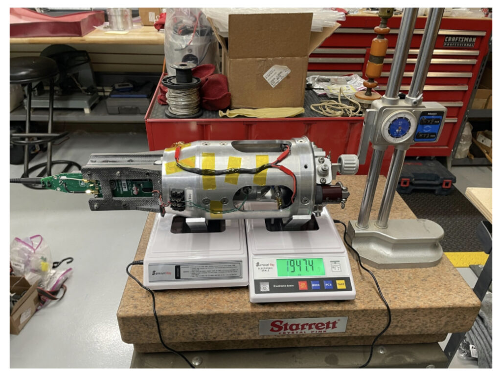
The image below shows the set up for longitudinal balancing of a payload:

Dual-weight scales with precisely placed mounring locations

Two identical scales are slightly modified to support the payload so that the longitudinal axis is parallel with the base of the scales and level.

After carefully measuring the distance between the centers of the two scales (6.760” in this example) the weight of the payload supported by each scale is noted in two orthogonal planes.  Using a moment balance calculation, the center of gravity is determined in each plane:

Averaging three measurements in plane 1, the scales showed 6.953 lbsm on the left side and 4.523 lbsm on the right scale.  Creating an arbitrary starting datum for calculation that is 0.7125” to the right of the right scale center point (that is, at the bottom of the payload base plate) allows the following center of mass balance:

Cg = (4.487 lbsm * 0.7125 in.) + (6.967 lbsm * 7.4725 in.) / (4.487 lbsm + 6.967lbsm)

​​​​= 4.824” from the datum.

Rotating the payload by 90 degrees and weighing again allows calculating the Center of Gravity in that plane, in this case, that value was:

​​​Gg = 4.881” from the datum.

Thus, the Cg appears—on average—to be offset by 0.057” between the two planes.

Balancing: Subtractive and Additive

Balance can be achieved either by subtracting weight from the top of and in the plane that shows the longer Cg distance (Plane 2, in this case) or by adding weight to the top of the plane that has the shorter Cg.  Conversely, weight could be added at some bottom location of Plane 2 or deducted from a bottom location on Plane 1. Note that any of these actions have effects on the rotational balance, which we will address in a future article.

Subtractive Balancing

We can estimate the amount of weight that needs to be deducted from the firstplane by deciding that the weight will be removed at 9.375” from the datum (a location at the top of the conical aluminum section, just below the fiberglass structure that supports the flight computer / transmitter in the image).

The mass required to move the Cg by 0.057” is then:

Mass Lost (or Gained) / New Total Mass = Change in Cg / Distance to New Mass

Adjustment Mass / (11.451 – Adjustment Mass) = .057 / (9.375” – 4.881”)

Adjustment Mass = 0.142 lbsm

This mass must be removed at equidistant locations from the rotational axis, that is, we will require two 0.071 lbsm axisymmetric holes in opposite sides of the payload at the required location.

We can estimate the drill depth assuming the use of a mill cutter.  The required cutting depth is then the cross-sectional area of the mill times the drill depth times the density of aluminum:

​​Mass to be removed = 0.098 lbsm. / cu. in. * (pi * r^2) * h

For a 0.5” mill cutter that depth is:

​​​0.071 = 0.098 * 3.1416 * (0.5 / 2)^2 * h 

​​​​​h = 3.69”

Obviously, this is impractical as the depth of aluminum at the subject location is only 0.125”.

Additive Balancing

The relatively large cutting operation required for subtractive balancing is due to the low density of aluminum.  Alternatively, we can estimate the additional mass required in the shorter of the two planes (Plane 1). Because we can use, for example, tungsten for the weight adjustment, it is possible to move the shorter Cgforward with much smaller but higher density balance weights.

Adding mass at a greater distance from the Cg will lower the mass required to achieve the needed shift.  If we consider adding mass at a location 13.375” from the datum location (on the cross bar near the top of the fiberglass structure that supports the flight computer / transmitter) we can calculate:

Adjustment Mass / (11.454 + Adjustment Mass) = .057 / (13.375” – 4.824”)

Adjustment Mass = 0.0763 lbsm

Noting that one-half of this is 0.03815 lbsm or 17.3 grams, we can observe that a standard tungsten weight used in “pinewood derby” cars of 0.25” diameter and 0.5” length weighs about 14 grams. Thus, drilling two axisymmetric holes at the required location and gluing the tungsten counterweights in place will produce a Gg offset close to the 0.057” adjustment required (see the comments below on the resolution of this system for locating the Cg).  Note that the two balance weights, in final form, need to weigh the same within a small margin or they will introduce a mass imbalance in rotation. We should also note that we are not here accounting for the mass removed to make the holes for the counterweights.

Verification

The final step is to remeasure the Cg in both planes and verify that they are within the resolution of the measurement system.  If not, another, smaller, adjustment in mass in the longer plane or an adjustment of the balance weight in the shorter plane may be required.

A Note on Accuracy

The relativity low cost scales used in this example resolve weight to 0.10 grams. However, multiple measurement in the same plane (achieved by gently pressing on the payload to reset the scales) shows that the scales are in fact accurate to about +/- 10 grams, about 0.3% of the total weight of the subject payload.

This means that the true resolution of this system with regard to differences in Cg between planes is about 0.015”, thus, once the Cg between the planes is within 0.15”, further adjustment is unlikely to increase accuracy using these relatively low-cost scales.


MTA work event, 2023-03-03

Dimitri Timohovich, RRS.ORG


Last weekend saw a big dent put into the bathroom project. On Friday, 3/3/23, I was able to install the 2 remaining pass-throughs, one for the water to enter the container and one to serve as part of the shower drainage.

Clean cut window and a look from the inside
Supply header pass-through in place.

I was able to also attach the main drainage line to the outside drainage line and set up to connect the shower drainage to the main line.

Saturday, 3/4/23, started out with nice weather and I was able to connect the water line from the pass through and run it to the pump area.  More PEX lines were run and a manifold was made for a bypass incase of pump failure.  Final attachments will need to be made.

Dave showed up just in time for the wind to pick up.  Meanwhile, I started to tie in the electrical and build a small control box with a main switch and voltmeter.  Unfortunately, Dave couldn’t stay long and after lunch I went back to more electrical work.  Meanwhile, the weather kept getting worse.  

Sunday, 3/5/23, was cold, very windy, and with scattered showers, so I packed up early and headed back to town.

Next event is coming soon. Progress and next steps to be discussed at the March 10th monthly meeting.

New plumbing feedthroughs
Voltmeter installed for checking battery health.

We are getting close to having the restroom become operational. We hope the weather continues to be favorable.