Tank Blowdown Math

by Prof. Dean R. Wheeler, Brigham Young University


EDITOR’S NOTE

This posting is reprinted from the original article written March 13, 2019 with permission from the author. This article was intended for chemical engineering students to size relief valves for pressure vessels, but it applies well to amateur liquid rocketry as many use a pressure fed system to deliver propellants to the engine.

The PDF of this white paper can be found below.

https://www.et.byu.edu/~wheeler/Tank_Blowdown_Math.pdf

The RRS has several members engaged with liquid rocket projects. An important part of analyzing the performance of those systems is the pressurization system that drives the propellant into the engine. The tank blowdown problem is useful to designing the system and estimating performance. This derivation goes through the thermodynamics of the general tank blowdown problem and should be a useful starting point for a pressure-fed liquid rocket project.


INTRODUCTION

This document provides a mathematical model for computing the rate of expelling gas through a small orifice or nozzle attached to a tank. Furthermore, two models are described for how fast the tank will depressurize. Related material on compressible flow can be found in fluid mechanics and thermodynamics textbooks and web pages.

Figure 1 shows the tank and associated nozzle. The narrowest diameter of the flow path in the orifice or nozzle is known as the throat region. The tank and throat regions are described with their own sets of equations.

Provided the tank is large and the throat is small, it will take many seconds to empty the tank and gas velocities in the main part of the tank will be much smaller than the speed of sound. This means that gas pressure, temperature, and density in the tank will be spatially uniform, though they will be changing in time. Thus, we describe the tank using a transient mass balance. One can compare this to a model in heat transfer known as lumped capacitance.

In the nozzle region however, gas velocity is large and there are large spatial variations in the gas properties. In addition, there is relatively little gas contained in the nozzle region. Thus, flowrate in the nozzle adjusts rapidly to match current conditions in the tank, making it seem as if the nozzle is operating at steady state. This approximation for the nozzle is known as quasi-steady state.
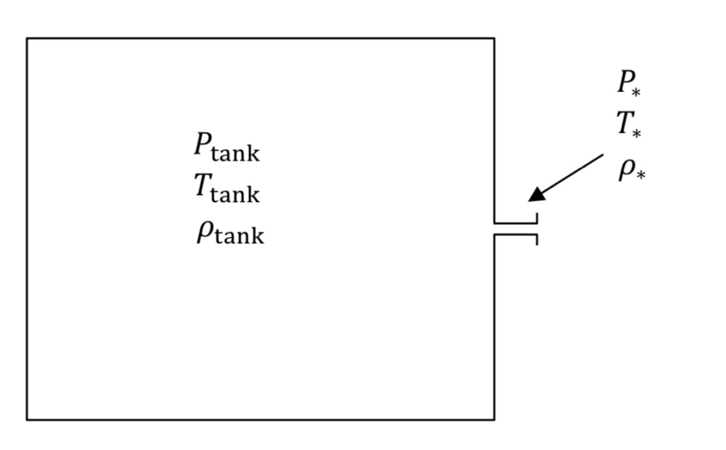
Figure 1: Schematic of a task with nozzle or orifice, allowing gas to exit. Italicized are variables that pertain to twokey regions. During blowdown every variable depends on time,

EQUATIONS OF STATE

The P, T, and rho variables in Figure 1 denote absolute pressure, absolute temperature, and density in the tank or the narrowest part of the nozzle or throat (denoted by an asterisk,*, subscript), respectively. Note that if tank pressure is given experimentally as a gauge quantity, it must be converted to absolute to be used in the equations below.

The first relationship between gas variables is given by an equation of state. The ideal gas law is a fairly accurate representation for air when pressure is less than around 10 atmospheres or 150 psia. It states that:
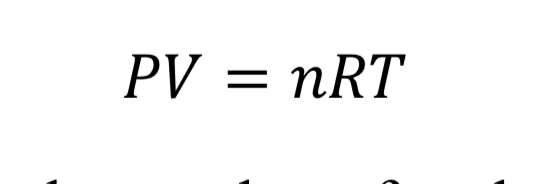
Figure 1: The ideal gas equation

where “V” is the volume of the gas, “n” is the number of moles, and “R” is the universal gas constant (8.31446 J/mol/K). With the introduction of the molecular weight, M (effectively 0.028964 kg/mol/K for air), and the substitution that density is mass over volume, rho = n M / V, the ideal gas law is changed to
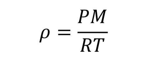
Equation 2: Density calculated from the ideal gas equation

This equation could be applied separately to the tank variables or to the thrust variables.

TEMPERATURE AND PRESSURE DURING EXPANSION

The second important relationship comes from figuring out what happens when gas in the tank or nozzle expands. When a gas expands, its internal energy is used to perform work on the surroundings, and the gas therefore tends to cool off. If the gas expands slowly, there is time for itmto absorb hest from its warmer surroundings and the expansion is essentially isothermal, meaning the temperature stays at its initial value or that of the surroundings.

On the other hand, if a gas expands quickly its temperature will drop dramatically. This is called adiabatic expansion, where adiabatic means no noticeable heat transfer from the surroundings (i.e. the walls of the tank). In adiabatic expansion, the pressure drops more rapidly than it would for an isothermal (slow) expansion. Adiabatic expansion could haolen inside the tank if it is emptying rapidly, but this depends on the relative sizes of thr tank and nozzle. On the other hand, adiabatic expansion certainly occurs when a gas moves from the tank through the nozzle region. In other words, here the gas is moving quickly and therefore expanding quickly.

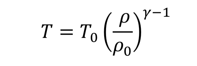
The thermodynamic relationships for pressure and temperature for reversible adiabatic expansion of a constant heat capacity ideal gas are:
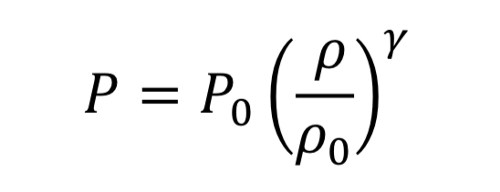
Equation 3A: Adiabatic pressure and density relationship
Equation 4A: Adiabatic temperature and density relationship

where the subscript, “o” indicates the initial state of the gas before the expansion started. This means if we know how the density is changing from an initial state to some later state, we can compute P and T as well. In the case of the nozzle, we apply the above equations as the gas travels between the tank and the throat. In the case, they become

Equation 3B: Adiabatic pressure and density relationship between tank and throat regions
Equation 4B: Adiabatic temperature and density relationship between tank and throat regions

The parameter, “gamma” , is the dimensionless ratio of specific heats ( gamma =. Cp / Cv ), and by statistical theory of gases, gamma = 7/5 = 1.4, for low temperature diatomic molecules, nitrogen (N2) and oxygen (O2) and so that value is used here.

CHOKED FLOW

Next, we need to determine the gas density in the nozzle when the tank is at a specified conditions. Recall that that the nozzle is treated as if it instantaneously responds to whatever state the tank is in. A fuller discussion of the nozzle flow equations can be found in other sources like textbooks that cover ideal compressible flow in nozzles.

Choked flow means that the flow is exactly at the speed of sound in the throat region. A higher speed cannot be achieved in the throat, regardless of upstream or downstream conditions. Thus, choked flow acts to limit how much gas flow can pass through a given size orifice, This is the reason why pressure relief valves on tanks must be properly sized to accommodate sufficient flow.

Choked flow happens for a large pressure drop across the nozzle or orifice, specifically if the upstream tank pressure meets the following condition relative to atmospheric pressure downstream from the nozzle:

Equation 5: Choked flow condition

Equation 5 is the origin of the rule of thumb or approximation that choked flow occurs for upstream pressure that is more than twice the value of downstream pressure (absolute). If the tank pressure drops below this limit, the speed of gas in the throat is subsonic, and less gas will flow than in the choked flow regime. The solution to subsonic flow in the nozzle is complicated and is less important to know because it is at the end of the tank’s discharge when pressure is low, and so will be neglected here.

The solution to choked flow in the throat region follows a simple relationship, derived from energy and mass balances:
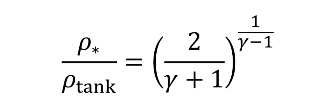
Equation 6: Throat to tank density ratio

This can be substituted from Equation 3B and 4B to determine pressure and temperature in the throat in terms of tank conditions.

For choked flow the throat velocity is exactly the speed of sound, which is what makes it easier to analyze. For ideal gases, speed of sound, c, is determined solely by temperature. Thus, we can relate throat velocity to throat temperature, and in turn to tank temperature:

Equation 7: Speed of sound at the throat

For example, if T_tank = 294 Kelvins, then c_o = 314 m/sec for air.

MASS FLOW RATE

Now we can determine the mass flow rate, “m_dot”, through the nozzle or orifice. This comes from the following standard relationship, applied at the throat, because that is where conditions are known:

Equation 8: Mass flow,rate at the throat

where “A_*” is the throat cross-sectional area given by

Equation 9: Area of a circle

and where “d_*” is throat diameter.

Dimensionless parameter, Cd, in Equation 8 is the discharge coefficient, accounting for friction between fluid and walls and a phenomenon known as vena contracta. In essence, Cd, is needed in Equation 8 because the effective area for fluid at speed, v_o, is somewhat smaller than actual throat area. Cd would be equal to 1.0 for a perfect (frictionless or thermodynamically reversible) nozzle: in practice for a smoothly tapering nozzle it might be as high as 0.98, while for a sharp-edged orifice it might be as low as 0.60. Anything that causes separation of flow from the nozzle wall or increases frictional contact will decrease Cd.

Making the appropriate substitutions into Equation 8 leads to an equation for mass flow in terms of readily determined quantities:
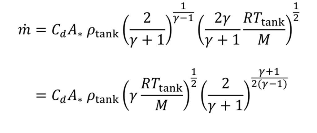
Equation 10: Mass flow rate in terms of readily determined quantities

Frequently in industrial situations, mass flow rates are expressed instead as volumetric flow rates corresponding to a gas at a standard temperature and pressure (even though the gas is not actually at that temperature and pressure). For instance, a mass flow meter used for gases may express mass flow as standard liters per minute (SLPM) or standard cubic feet per minute (SCFM). In other words, even though m_dot (mass flow) is the key value being measured, it is expressed as

Equation 11: Standard volumetric flow and mass flow rate

which requires knowing what rho_std value is programmed by the manufacturer into the flow meter. This can be determined from the ideal gas law, given specified P_std and T_std values. As an example, the American manufacturer, Omega, assumes a standard temperature “T_std” of 70 degrees Fahrenheit (294.26 Kelvins) and a standard pressure “P_std” of 1 atmosphere which equals 14.696 psia (101,325 Pscals) thus by the ideal gas law, the standard density “rho_std” would equal 1.2 kg/m3 for air (molecular weight 28.97 g/mole).

Combining Equations 10 and 11 and the ideal gas law leads to

Equation 12: Combining Equations 10 and 11 for standard volumetric flow rate

where “c_std” is the speed of sound at the standard temperature:

Equation 13: Standard volumetric rate and mass flow rate relationship

Makers of valves and orifices may provide an experimentally determined size parameter known as flow coefficient, Cv. For gases this dimensionless parameter can be converted to Cd*A_* by

Equation 14: Discharge area relationship4 to valve coefficient (metric units)

The key design principles resulting from the above analysis are, provided tank pressure is large enough to generate choked flow, that (1) mass flow rate of a gas through an orifice is proportional to throat area and tank pressure and (2) flow rate does not depend on downstream pressure.

TWO MODELS OF TANK BLOWDOWN

Equation 10 gives the rate of mass loss from a tank at a given gas density and temperature. To determine how long it will take to depressurize the tank, we must do a transient mass balance on the tank. The ordinary differential equation for this is:
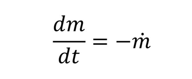
Equation 15: Change of mass in time

where “m_dot” comes from Equation 10 and “m” is the mass of gas in the tank. This in turn is:

Equation 16: Mass in the tank

where V_tank is the fixed tank volume. With these substitutions we get for the governing equation

Equation 17: Mass flow rate from the tank

To make things more manageable, let us create a discharge time constant called “tau”

Equation 18: Time constant for blowdown of a tank

where “c_o” is the speed of sound at the initial temperature “T_o” (i.e. at the beginning of blowdown)
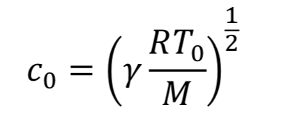
Equation 19: Speed of sound at initial conditions

With this new time constant, Equation 17 becomes:

Equation 20: Mass flow rate change in the tank

The last thing to do before solving this equation is figure out what to do with T_tank. We have two options:

ISOTHERMAL TANK ASSUMPTIONS

Assume gas temperature in the tank does not change in time, based on blowdown taking a long time so that heat can be readily absorbed from the walls. Thus, T_tank = T_o. This leads to Equation 20 becoming

Equation 21: Tank density change in time

which can be separated and integrated to give the solution

Equation 22: Tank density as a function of initial conditions

where “rho_o” is initial density in the tank. We then convert densities to pressure using the ideal gas equation.

Equation 23: Tank pressure as a function of initial conditions

The equation tells us how tank pressure varies with time, for an isothermal tank and choked exit flow.

ADIABATIC TANK ASSUMPTIONS

Assume the gas cools as it expands in the tank, due to no heat transfer from the walls, based on the blowdown taking a short time to complete. Thus, T_tank is given by Equation 4A. This leads to Equation 20 becoming

Equation 24: Mass flow rate from the tank

which can be separated and integrated to give a solution.

Equation 25: Density of the tank as a function of time

We then convert densities to pressures using Equation 3A for adiabatic expansion.

Equation 26: Tank pressure as a function of time

This equation tells us how tank pressure varies with time, for an adiabatic tank and choked exit flow. The tank temperature can likewise be predicted from Equation 4A.

Equation 27: Tank temperature as a finction of time

COMPARISON OF THE TWO MODEL ASSUMPTIONS

The isothermal and adiabatic models of tank blowdown can be considered two extremes, with the correct answer (i.e., with the true amount of heat transfer) lying somewhere in between them. Figure 2 shows an example of the respective blowdown curves (Equation 23 and 26). As noted previously, adiabatic tank conditions lead to more rapid pressure loss than do isothermal conditions.

The curves predict that the tank will have lost 80% of its original pressure at a time in the range of 1.3*tau < t < 1.6*tau. This shows the value of evaluating the variable, tau, to get an approximation of the time it takes to depressurize the tank.
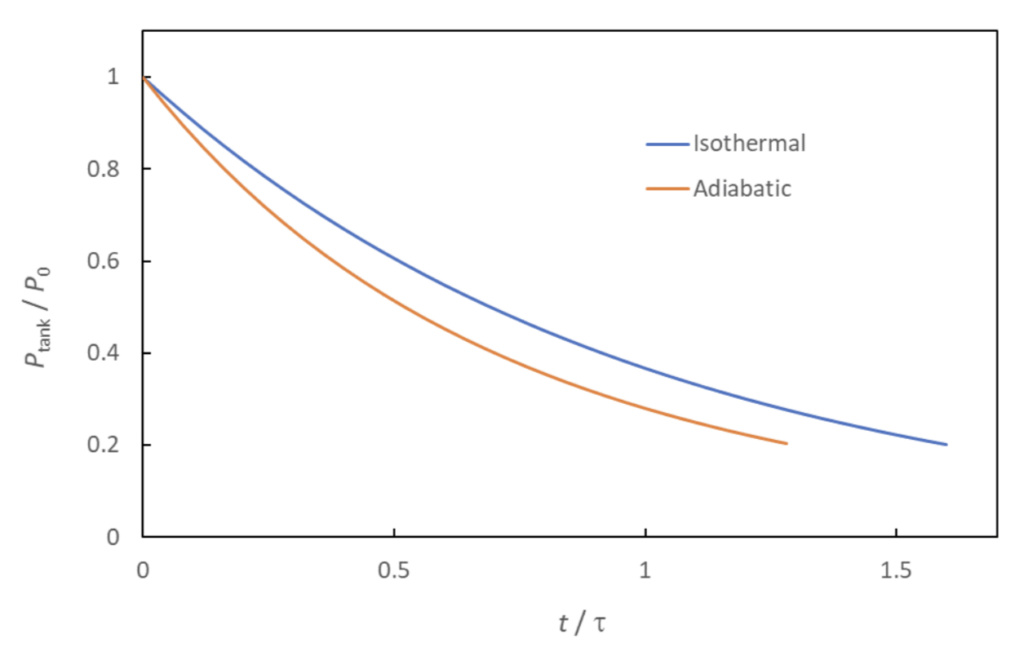
Figure 2: Comparison of isothermal and adiabatic blowdown curves.

MTA launch event, 2021-02-20

by Dave Nordling, Reaction Research Society


The Reaction Research Society held another launch event at the Mojave Test Area (MTA) on February 20, 2021. The weather was not cooperative for much of this day with wind gusts well beyond acceptable limits for launch (> 25 MPH). Our neighbor, Dave Crisalli and his Polaris Propulsion team, were using the Dosa Building as he had construction activities planned but were cancelled for that day. The RRS and Polaris Propulsion were glad to share the Dosa Building as we both made good use of the day.

The three planned objectives (weather permitting) for this MTA launch event were:

  • Build a new pit toilet restroom just north of the original site.
  • Conduct Solar Cat operations at the MTA
  • Conduct model rocket launches from Keith Yoerg’s new wire launcher array

THE ALL-SOLAR POWERED SOLAR CAT PROJECT

Bill Inman and his colleague, John Wells, made the long journey to the MTA from Nevada. Bill had made further improvements to the launching system and solar collector powering the Solar Cat steam rocket. He was able to and a remote tracking motor and drive system to further automate his solar concentrator, but several minor problems in setup prevented a launch that day.

Bill Inman and John Wells examine and prepare the solar collector system from the trailer at the east side of our MTA.
Photovoltaic panel mounted to the front of the collector to power the tracker.
Bill Inman and John Wells set up the latest iteration of the Solar Cat steam rocket from just west of the alpha and beta launch rails

Bill is striving to use an entirely solar powered system including a photovoltaic power system for his auxiliary functions. Because of the east to west passage of the sun through the sky, the steam rocket must be launched in a northerly direction. This is possible if done from the northern or western edges of our launch site.

Although the winds were excessive throughout most of the day, Bill could still conduct some assembly testing and even conduct steam rocket heating operations while keeping the rocket secure on the ground. Launch would only be attempted if the winds lowered in that time. Sadly, much of the day passed in correcting minor problems and system tests. The system proved ready but insufficient sunlight remained that day and launch would have to be conducted from the MTA at the next opportunity.

BUILDING A NEW PIT TOILET AT THE MTA

The society has been examining many improvements to our Mojave Test Area which has stood for over 65 years. The site has been improved over the many years but time has taken its toll and renovations are needed.

The top priority selected by our membership and visitors was the restroom facilities. Our short term plan was to build a second pit toilet while we work on plans for a more luxurious option in the longer term. This effort is viewed as a stopgap solution which will serve our society for at least a few years. Dmitri Timohovich and Wilbur Owens contributed greatly to this effort. With the many people we had at the site, we were able to start and complete the project with time to spare that day.

Our starting point for the project.
Wilbur operates the backhoe to get the trench dug for the sonotube. While Dmitri completes the wooden deck for the new pit toilet,
The precarious job of installing the sonotube once the pit is at the proper depth.
After getting sonotube vertical, the rest of the pit was filled with a few bucket loads of dirt and a few of us with shovels.
The new restroom deck gets placed and aligned with the new sonotube.
The toilet booth is removed from the original concrete platform. Our president, Osvaldo Tarditti, pauses a moment to consider how much crap our society has taken from our visitors and members alike,
The toilet booth is placed on the new platform, but first some further trimming of the sonotube must be done,
RRS secretary, Keith Yoerg, and RRS member, Dave Nordling, stand at the original concrete platform now filled flush to the surface with dirt. The task is nearly complete.
Once firmly affixed to the new platform, the toilet booth was fit checked by Dmitri Timohovich. He is signalling that our pit toilet is now ready for business.

The pit toilet project was a success thanks to both our members providing their physical and material labor and the careful planning and coordination that took place starting in this new year. This improvement project will be only one of several to come. We hope to make our remote testing site both more functional but also a bit more comfortable to all who visit us after many hours drive from the city.

LAUNCHING ROCKETS FROM A NEW MULTI-WIRE RAIL STRUCTURE

With the last hours of the day upon us, the winds had subsided to a more reasonable speed. Keith Yoerg had a few model rockets prepared for launch with commercial motors. He had also built a multi-wire launcher which is a convenient way to display and launch several small vehicles successively.

Max Timohovich (left) views the Baby Bertha and the Big Bertha rockets as they sit on the launch rail made from PVC pipe and fittings.

Second thing introduced at this MTA launch event was a four channel launch box built by Dmitri Timohovich. With a clean wood finish and a rugged latched case, this box proved its function well with the launch of three model rockets that day.

The new launch box was tested at the 2/20.2021 MTA launch event

After some glitches with the electric matches, Keith was able to launch and recover the Baby Bertha (A8-3) and the Big Bertha (A8-3) rockets. We got excellent footage of these classic model rocket types. The last of the three launches was the slightly larger Star Orbiter (E16-6) which left the rails cleanly and the recovery system deployed without issue. Although the winds had subsided sufficiently at ground level, the higher level winds carried the Star Orbiter for a long horizontal trek west well beyond the property line, After some searching, the Star Orbiter was lost to the desert hoping to be recovered

Baby Bertha leaps off the wire rail with its tiny A8-3 motor,
Big Bertha comes back under its parachute landing just to my left. This great video can be seen on the RRS Instagram account.
The last photo of the Star Orbiter as it sits on the pad before the wind carried it far to the west.

IN CLOSING

The team cleaned up the area and put away the gear at sunset. We talked about setting the next launch date in March 2021. We hope to have a new date set soon, likely after March 12th.


February 2021 Virtual Meeting

by Keith Yoerg (RRS Secretary)


The latest meeting of the Reaction Research Society took place this past Friday, February 12th and had 19 attendees – including several guest presenters. The meeting started with a discussion of the logistics surrounding the upcoming MTA launch & work event next Saturday, which overlaps with ongoing construction on Dave Crisalli’s adjacent land. The construction workers will be utilizing some of the MTA facilities, and following a discussion among RRS members it was agreed that the planned launch & work event could still be held without interfering with construction activities.

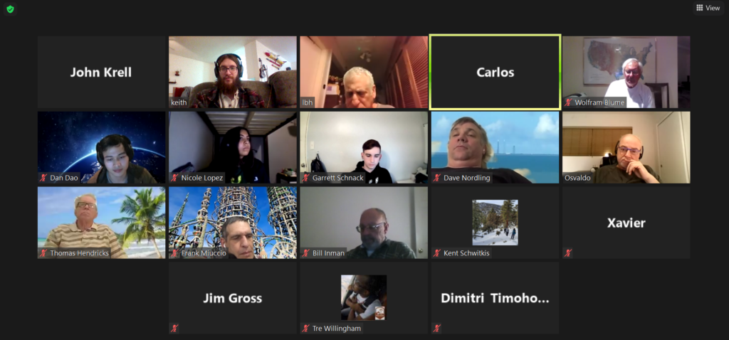
Screenshot of discussion during the monthly meeting

GUEST PRESENTATION – POLY RABBOTICS

Members from the Long Beach Polytechnic High School First Robotics Competition team made a presentation on their project and the adjustments they have had to make due to COVID-19 restrictions. Without being able to meet in person to fabricate and assemble parts on their robot, the student-run group has had to shift their work to virtual workshops and at-home competitions to keep their skills sharp. One such competition required teams of 3 to build a mini-robot able to climb a pole.

Title slide for the Poly Rabbotics presentation – checkout their cool logo!

Their team is currently meeting 3 times a week to prepare for competition later this year, which features an altered “at-home” layout. Despite the many challenges, it’s clear that this team is making the best of the situation and continuing to help their members gain knowledge and improve their skillsets.

GUEST PRESENTATION – CSULB ROCKETRY

A second guest presentation was provided by members of the Cal State Long Beach Rocketry team. They compete in the NASA Student Launch Competition which challenges teams to design, build, and fly a rocket to between 3,500 ft and 5,500 ft while carrying a drone payload. The drone must deploy away from the rocket and fly to a specific position.

Presenter Dan Dao in the CSULB campus lab in Feb. 2020.

Fortunately, this team has been able to continue fabrication work on their rocket by following strict precautions to avoid the spread of COVID-19. Their shop site is on the Starbase campus at the Los Alamitos Joint Forces Training Base, and only a small number of specific team members are allowed on site. During competition last year the team placed 12th out of 46 total entrants, and they hope to finish in the top-10 this year.

PLANS FOR THE UPCOMING MTA EVENT

The primary focus for the upcoming MTA event is construction of a new pit toilet on the property. Dimitri plans to build a wooden platform this week and transport it out to the MTA site on Saturday, along with a sonotube liner for the pit. The wooden platform will rest on posts dug into the ground, and once in place we will remove the port-a-john from its current concrete plinth and secure it to this new platform. Work on welding the new plate on the vertical test stand, clearing nearby brush, and other site maintenance could take place if time allows.

Bill Inman plans to continue work on his solar-powered steam rocket, which uses mirrors to heat water with sunlight. Seemingly unsatisfied with any energy source other than the flaming ball in the sky, Bill has decided to modify his setup so that the tracking mechanism (which automatically tilts the solar collector to track the sun) is powered by a solar panel. Bill will be testing this new setup at the next event and may attempt a launch of the steam rocket.

Mockup of the internals for Dimitri’s hybrid rocket module

Keith will bring his high power solid rockets “Charlie Horse” and “X2”, and intends to launch at least one of them. The goal of the launch will be to test whether the LoRa GPS trackers, which have been discussed at previous RRS meetings, can be used as a cheap way to track rockets. Dimitri is finishing work on a 4-pad solid rocket launch controller (a layout is shown above) as well as a water rocket launch controller, both of which should be ready for testing on Saturday. A discussion on what food should be grilled at the event was concluded immediately after Dave Nordling’s suggestion – brats.

RRS HISTORY

An additional guest with a connection to the society joined us for this meeting – Tom Hendricks. He was a member of the RRS from 1959 – 1960 while he was a student at Glendale High School. He recounted launching micrograin rockets fueled by zinc dust and sulphur, displayed a rocket nozzle he had once launched, and recalled that the only test stand at the MTA site at that time was a lone I-beam (there’s a lot more on-site now!).

Tom also mentioned that back when he was an active member, the majority of the fabrication for the RRS was provided by 1 society member who had a lathe in their home. Many current members were excited to have Tom back in the fold, and he expressed a desire to join us for an event at the MTA soon. We’re looking forward to having him!

EXECUTIVE COUNCIL MEETING RECAP

The final item of business was a recap of topics covered during the January 2021 meeting of the RRS executive council. Council members have received the recommended edits to the constitution from the 2020 Constitutional Committee, and expect to have a version ready for the voting membership to review during the March meeting.

Image of Chris Lujan explaining different setups for security cameras

Council members Keith and Larry have been working on plans to install a security camera at the MTA, and presented the current status of the project. The goal is to have a network hotspot run WiFi security cameras. The project will start with the installation of a hotpot in the Dosa building (once shipped from backorder). The plan is to power the hotspot with a solar panel and determine the installation location that provides the maximum WiFi signal range. This will allow for optimum placement of WIFi security cameras. Chris Lujan has a lot of experience with home security cameras as a result of personal research, and shared that knowledge to help with the project.

NEXT MONTHLY MEETING

The next RRS monthly meeting will be held virtually on Friday, March 12th at 7:30 pm pacific time. Current members will receive an invite via e-mail the week of the meeting. Non-members can request an invitation by sending an email to:

secretary@rrs.org