Liquid Rocket Components: Pyrotechnic Valves

by Tom Mueller


Editor’s Note: This is a reprinting of the original article written by RRS member, Tom Mueller on the subject of pyrotechnic retin-a actuated valves around 1995 (?). He mentions the build of two different rockets (the XLR-50 and the Condor) and a hypergolic rocket he intended to build after this article was written. We hope to gather more photos and details about these rockets and display them in future improvements to this posting. For now, please enjoy the subject matter as the information is very relevant today to amateur builders of liquid rockets. The RRS has been very active lately in re-exploring liquid rockets. The society thought this would be a timely and interesting subject to share with our readers.

For any questions, please contact the RRS secretary, secretary@rrs.org


For an amateur rocketeer seeking to build a liquid rocket, one of the most difficult components to obtain or build are remotely operated valves. A liquid rocket will require at least one valve to start the flow of propellants to the combustion chamber. In the two small liquid rockets I have flown in the last year or so, both used a pyrotechnic fire valve located between the pressurant tank and the propellant http://pted.org/Cytotec.php tanks. The propellants were held in the tanks by burst disks (or equivalent) in the propellant run lines. When the fire valve was actuated, the sudden pressure rise in the propellant tanks blew the burst disks, allowing propellant to flow to the injector. This method of controlling the flow to the rocket allows the use of only one valve, and eliminates liquid valves.

In the case of the first rocket, the XLR-50 which flew in October 1993, elimination of the liquid valve was important because the oxidizer was liquid oxygen, and a small cryogenic compatible valve is very difficult to construct.

For the second rocket, which flew in October 1994, the small size prevented the use of liquid valves. In fact, the single pyro valve I used was barely able to fit in the 1.5 inch rocket diameter. In this article I will describe the design of the valves that were used on these two vehicles, and variations of them that have been used in other rocket applications.

FIGURE 1: XLR-50 pyro-technic “fire” valve

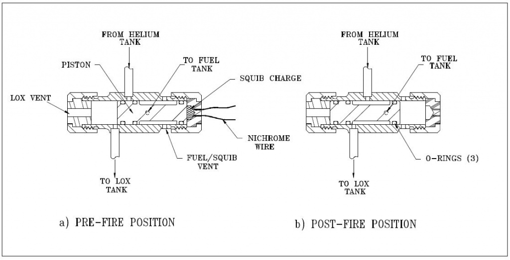
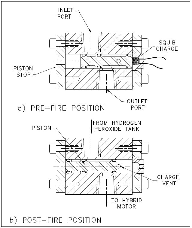
The valve shown in Figure 1 consisted of a stainless steel body with a 0.375 inch diameter piston. The O-rings were Viton (material) and the squib charge was contained in a Delrin plastic cap. The Delrin was used to prevent shorting of the nichrome wire, and also to provide a frangible fuse in case the squib charge proved to be a little too energetic. In practice, I’ve never had the Delrin cap fracture.

The inlet and outlet lines to the tanks were silver brazed to the valve body. The valve was tested many times at inlet pressures of up to 1000 psi without any problems, other than the O-rings would need replaced after several firings due to minor nicks from the ports. To help alleviate this problem, the edges of the ports were rounded to help prevent the O-ring from getting pinched as the piston translates. This was accomplished using a small strip of emery cloth that was secured in a loop in one end of a short length of 0.020-inch stainless steel wire. The other end of the wire was clamped in a pin vise which in turn was chucked in a hand drill. As the wire was rotated by the drill, the emery was pulled snugly into the port, where it deformed into the shape of the inlet, and rounded the sharp edge. I used WD-40 as a lubricant for this operation, allowing the emery to wear out until it would finally pull through the port. I repeated this process a few times for each port until the piston would slide through the bore without the O-rings snagging the ports.

Another requirement is to lubricate the O-rings with a little Krytox grease. This helps the piston move freely and greatly reduces the problem of nicked O-rings.

FIGURE 2: Fire valve for a micro-rocket

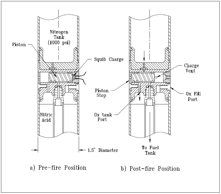
The pyro valve I used in the 25 lbf thrust micro-rocket that was launched in October of 1994 is shown in Figure 2. This valve was identical in operation to the XLR-50 valve, with the major difference being its integration into the vehicle body. The valve body was a 1.5 inch diameter aluminum bulkhead that separated the nitrogen pressurant tank and the oxidizer tank. Because of the very small diameter of the rocket, the clearances between ports and O-rings were minimized, just allowing the valve to fit. The fuel outlet port was located at the vehicle center, providing pressure to the fuel tank by the central stand pipe that passed axially down the oxidizer tank. The piston stop was a piece of heat-treated alloy steel that was attached to the valve body by a screw. This stop was originally made from aluminum, but was bent by the impact of the piston in initial tests of the valve. The black powder charge in the Delrin (https://openoralhealth.org/prednisone/) cap was reduced and the black powder was changed from FFFg grade to a courser FFg powder, but the problem persisted. The stop was re-made from oil hardening steel and the problem was solved. In this application, the port diameters were only 1/16 inch so only a small amount of rounding was required to prevent the O-rings from getting pinched in the ports. The valve operated with a nitrogen lock-up pressure of 1000 psi.

FIGURE 3: Fire valve for Mark Ventura’s peroxide rocket

A more challenging application of the same basic valve design was used for the fire valve of Mark Ventura’s peroxide hybrid, as shown in Figure 3. This was the first application of this valve where liquid was the fluid being controlled, rather than gas. In this case the liquid was 85% hydrogen peroxide. The second difficulty was the fact that the ports were required to be 0.20 inch in diameter in order to handle the required flow rate. The valve was somewhat simpler than the previous valves in that only a single inlet and outlet were required. The valve body was made from a piece of 1.5-inch diameter 6061 aluminum, in which a 1/2-inch piston bore was drilled. The piston was also 6061 with Viton O-rings, which are peroxide compatible. The ports were 1/4-inch NPT pipe threads tapped into the aluminum body. The excess material on the sides of the valve was milled off, so that the valve was only about 3/4 of an inch thick, and weighed only 4 ounces. Even though the piston size was 1/2 inch, the same charge volume used in the 3/8 inch valves was sufficient to actuate the piston.

In testing the valve with water at a lock-up pressure of 800 psi, I was pleased to find that even with the large ports, O-ring pinching was not a problem. One saving factor was that the larger size of the ports made it easier to round the entrances on the bore side. The valve was tested with water several times successfully before giving it to Mark for the static test of his hybrid.

The only problem that occurred during the static test of hybrid rocket was that the leads to the nichrome wire kept shorting against the valve body. Three attempts were made before the squib was finally ignited and the engine ran beautifully. I have since been able to solve this problem by soldering insulated 32-gauge copper wire to the nichrome wire leads inside the Delrin cap. In this way, I can provide long leads to the valve with reliable ignition.

My next liquid rocket is a 650 lbf design that burns LOX and propane at 500 psia. This engine uses a Condor ablative chamber obtained from a surplus yard. For this reason, I call it the Condor rocket. This rocket uses a scuba tank with 3000 psi helium for the pressurant. I decided to build a high pressure version of my valve as the helium isolation valve for this rocket. When firing this rocket, just prior to the 10 second count, this valve will be fired, pressurizing the propellant tanks to 600 psi. I assumed going in to this design that the O-rings slipping past a port simply wasn’t going to work at 3000 psi.

At these pressures, the O-ring would extrude into the port. In order to get around this problem I came up with the design shown in Figure 4.

FIGURE 4: High pressure helium valve for Condor rocket

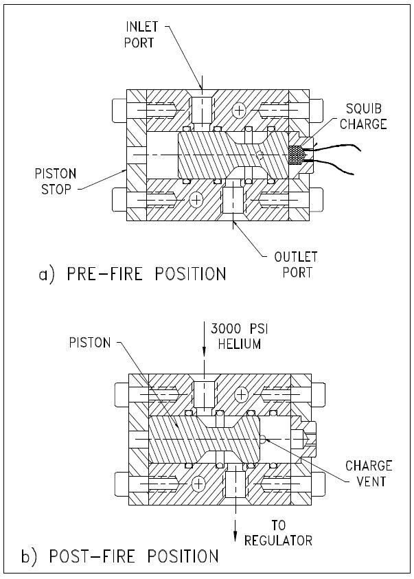
For this valve, the O-ring groves were moved from the piston to the cylinder bore of the valve body, so the O-rings do not move relative to the ports. The piston is made from stainless steel with a smooth surface finish and generous radii on all of the corners. The clearance between the piston and the bore was kept very small to prevent extrusion of the O-rings. The valve operation is similar to the one shown in Figure 3, and the valve body is made in the same way except female AN ports were used rather than NPT ports. When the valve is fired, the piston travels from the position shown in Figure 4a to that shown in Figure 4b. During this travel, the inlet pressure on the second O-ring will cause it to “blow out” as the piston major diameter translates past the O-ring groove. The O-ring is retained around the piston, causing no obstruction or other problems. This valve has been tested at 2400 psi inlet pressure with helium and works fine. It will be tested at 3000 psi prior to the first hot fire tests of the Condor rocket next spring.

As a side note, essentially an identical valve design as the one used on the Condor and Mark’s valve is a design shown in NASA publication SP-8080, “Liquid Rocket Pressure Regulators, Relief Valves, Check Valves, Burst Disks and Explosive Valves”.

A second pyro valve is used on the Condor system as shown in Figure 5. This valve is used to vent the LOX tank in the event of a failure to open the fire valve to the engine.

FIGURE 5: Emergency vent valve for LOX tank, Condor rocket

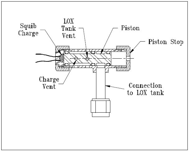
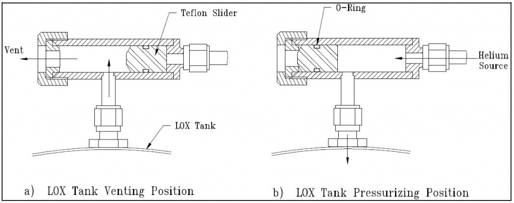
When the propellant tanks are pressurized by the helium pyro valve, the LOX tank auto vent valve (shown in Figure 6) closes. If the engine is not fired after a reasonable amount of time, the LOX will warm up, building pressure until something gives (probably the LOX tank). The pyro valve shown in Figure 5 is used as the emergency tank vent if the engine cannot be fired. The valve body is stainless steel with a stainless tube stub welded on for connection to the LOX tank. This valve has been tested to 800 psi with helium and works fine. In this case, some ‘nicking’ of the O-rings can be tolerated because the O-rings are not required to seal after the valve is fired. The ports in the bore are still rounded, however, to prevent the O-rings from getting nicked or pinched during assembly of the valve.

Even though it is not a pyro valve, I have shown the LOX auto-vent valve in Figure 6 because this design has proven to be very useful for venting cryogenic propellant tanks without requiring a separately actuated valve or control circuit. The valve uses a Teflon slider that is kept in the vent position as shown in Figure 6a.

This allows the tank to vent to the atmosphere, keeping the propellant at its normal boiling point. When the helium system is activated, the pressurant pushes the slider closed against the vent port, sealing off the LOX tank, as shown in Figure 6b. An O-ring is used around the slider to give it a friction fit so the aspiration of the LOX tank does not “suck” the slider to the closed position. This problem happened to David Crisalli (fellow RRS member) when he scaled this design up for use on his 1000 lbf rocket system. I have used this design on the LOX tank of my XLR-50 rocket, which used a 1/4-inch diameter slider, and on the Condor LOX tank, which uses a 1/2 inch slider. In both cases the vent valve worked perfectly.

FIGURE 6: Automatic LOX tank vent valve

The main fire valve on the Condor rocket is a pair of ball valves that are chained together to a single lever so that both the fuel and oxidizer can be actuated simultaneously for smooth engine startup. For static testing of the rocket, I will use a double-acting air cylinder to actuate the valves. For flight, however, I plan to use a pin that is removed by an explosive squib to hold the valve in the closed position. When the squib is ignited, the pin is pulled by the action of the charge on a piston, allowing the valves to be pulled to the open position by a spring. This method may not be very elegant, but it is simple, light, and packages well on the vehicle. David Crisalli has successfully employed this technique on his large rocket.

That covers the extent of the pyro valves I have built or plan to build so far. In the next newsletter, I will present the design and flight of the small hypergolic propellant rocket that used the valve shown in Figure 2.


Lawn Atlas Missile Base tour

From the ancient armies of China and India and the 19th century British armies using solid rockets in combat, to Von Braun’s work in Nazi Germany and Robert Goddard’s work with the U.S. Navy during the Second World War, the history of rocketry can not be told without mentioning the military aspects of these powerful devices. Modern rocketry at the dawn of the Space Age has roots in one of the most lethal weapons in mankind’s history.

A few years back (June 2014), my wife and I arranged a tour of an unusual piece of Cold War history in the middle of Texas. Larry Sanders, our gracious host is the owner of a former nuclear missile site just outside of the small town of Lawn, Texas. Through his hard work, he has begun to restore his own Cold War museum at this lonely piece of land adjacent to the rolling Texas plains and pastureland.

Longhorn steer grazes on the Texas prairie next to the Lawn Atlas Missile Base

This area, now called the Lawn Atlas Missile Base (LAMB) was once a first-generation Inter-Continental Ballistic Missile (ICBM) site near the small town of Lawn, Texas, less than 20 miles from Abilene, home to Dyess Air Force Base (AFB). Larry gives tours to schools and other interested parties in the local area of central Texas. He’s also been in the local and regional news for his work in restoring his missile silo into a unique historical site for the public.

Lawn Atlas Missile Base from Google Earth satellite imagery

Larry Sanders article – The Eagle

The Atlas ICBM Highway in central Texas (Texas Highway 604, south of Interstate 20)

Larry Sanders gives a tour of the Lawn Atlas Missile Base site outside of Lawn, Texas

In the early days of the Cold War era, the United States and the Soviet Union were in a race to develop launch vehicles to deliver nuclear warheads to the other side of the world from home and friendly territory. The early ICBM’s were liquid fueled rockets based on the higher performance over solid rocket motors of that time. Liquid oxygen (LOX) and kerosene (RP-1) were common high performance propellants in the late 1950’s and early 1960’s (and still commonly used today). The Atlas rocket stood 82.5 feet tall and 10 feet in diameter and with a gross lift-off weight of 268,000 pounds and a total thrust at sea level of 375,000 pounds from all three of its engines could deliver a W38 nuclear warhead over 9000 miles away.

The basic parts of the Atlas F missile

The Atlas rocket designed and built by Convair in San Diego, California, in the 1950’s. The Atlas used a unique vehicle staging concept called “a stage-and-a-half.” Staging of early rocket vehicles at that time was difficult and often plagued with failures. In the 1950’s, there was a concern about reliably igniting the second stage engines in the thin atmosphere at high altitudes. To counter this, the engineers at Convair devised a vehicle that would use a single set of RP-1 and liquid oxygen (LOX) tanks and rapidly ignite all three engines with pyrotechnic cartridges at the same time on the ground. In the middle of ascent, the booster segment would drop away thereby shedding the weight of the two booster engines with their associated pumps in flight. By doing this, the Atlas would finish the mission with only the middle sustainer engine to the end of the flight as the vehicle became lighter.

Rocketdyne MA-3 engine cluster for the Atlas stage-and-a-half rocket

Rocketdyne of Canoga Park, California, built the complex MA-3 engine system for the Atlas ICBM that had two outboard booster engines and a central sustainer engine. The MA-3 engine had a separate turbopump and gas generator for each of the three engines arranged in a line. The MA-3 engine also had two small vernier engines for roll-control, one on opposite sides over the sustainer.

Rocketdyne MA-3 booster engine, LR89-NA-5; two units

Rocketdyne MA-3 sustainer engine, LR105-NA-5; single core engine

Rocketdyne MA-3 vernier engine used on Atlas F vehicle

Atlas booster with the stage-and-a-half concept; outside booster engines fall away leaving the sustainer engine to finish the flight

The Atlas was the first operational ICBM in the American arsenal during the height of the Cold War. Twelve missile bases such as the one near Lawn, Texas, were clustered in around a central strategic command center, a U.S. Airbase in that region. In this case, Dyess Air Force Base in Abilene, Texas, is the former hub of this set of twelve SM-65 Atlas-F type missile sites.

SM-65 Atlas Missile Sites throughout the United States in the 1960’s

Lawn Atlas Missile Base location with respect to Dyess AFB in Abilene, Texas

The Atlas-F type was the last and most advanced version of the SM-65 series. With the RP-1 kerosene fuel loaded and waiting on standby, the Atlas missile was raised vertically from an underground silo to then be tanked with its cryogenic oxidizer (LOX). Air separation plants and special cryogenic liquid handling equipment were required to fuel these first-generation missiles. During its service life, the US Air Force maintained this land-based system to be ready to launch from the surface of the silo within minutes with just a small highly-trained crew.

Atlas-F, SM-65 ICBM in testing

Today, just a few things remain at the surface including the massive, reinforced concrete silo door slab at the Lawn Atlas Missile Base. Two doors are built into the roof where the missile was lowered and raised from its protective silo in the ground.

Lawn Atlas Missile Base – silo and ground access

Atlas-F missile silo as seen from the surface

Top side panaroma of the LAMB site

The Atlas E and F models were the first American ICBM’s to have an on-board computer for guidance using an inertial navigation system. The missile silo had a fixed sighting station to finely calibrate the missile guidance package to make it ready to accurately strike it’s target on the other side of the world. Some parts of this equipment still remain at the site.

The sighting equipment slab facing to the north of the missile silo seen in the background

Atlas ICBM guidance system using an optical sighting apparatus from within the silo

Remnants of communication equipment left at the site

An old antenna mount at the missile site

In the site’s operational period, there were a few small quonset huts at the surface to park servicing equipment for the missile and the silo. Some of the original foundations from these structures still remain at the site as can be seen in the satellite view.

Sketch of the Atlas missile ground support crew and trailers

Atlas F missile base with quonset hut support buildings

Atlas-F perched on the launch table with the blast deflector in place.

Atlas missile stored within its protective silo, erector structure and lifting equipment can be seen

Atlas silo and its underground control room / missile lifted and ready for launch

Our tour started at the protruding angled structure with the surface door angling down below the ground through a convoluted path to the next door.

Atlas F silo – ground access

Ground level door going into the Launch Command Center (LCC) of the Atlas F missile silo; the emergency escape hatch from the LCC can be seen to the right

Down the stair past the first door at ground level

The path from the ground access door leads down two flights of stairs to a couple of turns leading to a pair of entrapment doors. Beyond the entrapment doors are another pair of vault doors. At the LAMB site, a vintage Coke machine is between the two vault doors. Beyond the vault doors leads to a two-floor stair case giving acccess into the round two-floor Launch Control Center (LCC).

entrapment doors in red; the two vault doors in blue

first turn at the bottom of the stairs

the first of two simple doors just around the first corner

The first of two vault doors leading into the stairwell going into the LCC

Vintage (1960’s) Coke machine just behind the first vault door

Vault door latching mechanism

Mechanical vault door actuator from the inside

Once past the radiation-resistant vault door, the two man crew would descend a two-flight set of stairs to access the two-levels of the round LCC. A vintage Coke machine was just behind the door which was a little bit of civilization inside this rugged castle. The whole missile silo was very cool despite the summer heat at the surface, but the humidity inside of the barren silo was very high. Larry said that he very often had to spread desiccant and was frequently combating the mold that would flourish in the moist darkness.

Stairwell access to the Atlas-F LCC

Plate steel stairwell, entering the top floor of the LCC

Bottom of the stairwell, access to the lower deck of the LCC

The Launch Control Center is a two-floor “pillbox” cylinder bunker that housed the crew and the command equipment for operating the missile and the silo equipment. When the site was decommissioned, nearly all of this equipment was removed leaving only the bare walls and only a few non-military items. Having studied the subject and learning what he could from past missileers, our tour guide Larry provided details of where the crew slept, ate and conducted their duties all underground behind the vault door protected from nuclear attack from above.

Identification of equipment and features inside of the LCC

Nearly all of the original wiring and electrical fixtures were stripped out, so Larry has worked to slowly bring back ambient lighting into the LCC, or at least enough to safely conduct tours. Some of my pictures did not turn out so well in the low light, but the LCC had a lot to see.

Launch Control Center (LCC) of the Atlas-F missile silo

top floor inside the LCC in the Atlas-F missile silo

Crew cots around the circumference of the circular LCC (fuzzy from the low light)

Emergency escape hatch from the LCC

Kitchen area inside the LCC, much of this equipment was added (such as the microwave oven)

American eagle emblem hangs just above the kitchen area in the LCC

The lower level had housed the control equipment. Much of this equipment including the electrical fixtures were stripped away. What remains is an old circular photo darkroom and a really nice poster showing the Atlas SM-65 missile.

Picture of the Atlas SM-65 missile next to the circular darkroom for processing camera film

From within the stairwell at the lower level of the LCC, it’s a two-man job, always

Lower level in the LCC

Another view of the lower level of the LCC

The two-story LCC has an access tunnel leading to the missile silo. This circular path had a flat metal grating floor with a corrugated metal piping wall. This access tunnel was heavily corroded from the years of trapped moisture from the missile silo slowly filling with water as the ground water slowly bleeds through the small pores of the concrete. This is a common problem in subterranean structures, like missile silos. My pictures of this access tunnel were difficult to take from the low light conditions even with the camera flash feature. Need a boost in focus and productivity? Look no further! Modafinil is here to help you stay sharp and on top of your game. Say goodbye to groggy mornings and hello to a clear mind ready to take on any challenge. Whether you’re a student cramming for exams or a busy professional juggling multiple tasks, modafinil can give you the mental edge you need.

Circular access tunnel between the LCC and the Atlas missile silo

LCC access tunnel with silo blast doors

Corrugated metal walls of the access tunnel with empty electrical cable trays

A slightly better view of the access tunnel when looking back at the lighted stairwell

A view back at the access tunnel and silo blast doors from the overhanging deck in the missile silo

The missile equipment and silo structures have been stripped out of the silo during decommissioning leaving a dark cavernous cylindrical vault. Larry had a make-shift metal deck installed just at the edge of the opening to the silo, with a rope ladder leading down to a floating platform he set at the waterline.

A look over the edge of the metal deck just past the access tunnel entrance into the missile silo

overhanging metal deck into the missile silo

view looking down into the empty cavernous missile silo; it’s really hard to appreciate just how huge it is inside

Another view of the missile silo interior wall showing the metallic hard point connections for what might have been the missile elevator equipment to bring the rocket to the surface for launch; only the embedded equipment in the walls remain to rust

The two folding doors remain in the down position as the hydraulic piston actuators to open the doors were moved during decommissioning

Over time, rainwater would leak in from the silo doors at the top. Also, groundwater slowly seeps through the concrete filling the silo roughly half full of very clean, very fresh water. Larry is not entirely sure what, if anything, is remaining down at the bottom of the silo. Divers had once expressed interest in exploring the bottom of the silo, but thus far, no one has explored the bottom. My pictures really do not do justice to this impressive site of being within this empty silent tomb. Are you tired of living with chronic pain? Tapentadol may be the solution you’ve been searching for. As a powerful pain medication, it’s designed to provide fast and effective relief for various types of pain.

Looking up at the silo door in the slab from inside of the missile silo

Floating platform within the empty Atlas-F missile silo full of fresh groundwater

After seeing the missile silo, we returned to the LCC to examine some of the posters and documents Larry had collected on the Atlas missile and the missile base.

Collection of photos and Atlas missile silo information

Location of the Lawn missile base in the set of 12 surrounding Dyess AFB in Abilene, Texas

Figurative drawing of the Atlas F missile silo, on display in the LCC

poster of the Pocket Rockets in Texas

As the Atlas was being deployed as weapon, the rocket fulfilled an important early role in the manned spaceflight program. The first Americans in space, Alan Shepard and Gus Grissom, flew on Redstone rockets, but were unable to reach orbit. John Glenn, the first American to orbit the Earth in 1962, did so in his Friendship 7 Mercury capsule fitted on the more powerful Atlas used as a manned spaceflight vehicle.

An Atlas ICBM adapted to launch the Mercury capsule piloted by John Glenn

John Glenn, the first American to orbit the Earth, catching a ride on an Atlas.

Atlas-Mercury 6 launch

Although the Atlas had a fairly short operational history as an ICBM (1961-1966), derivatives of the same Atlas launch vehicle design continued to serve an important role as a space launch vehicle for military, government and commercial payloads. The remaining Atlas F vehicles became space launch vehicles with the last one flying out in 1981. The Atlas F could loft a 820 kg (1800 lbm) payload to a 185 km polar orbit. Don’t let health concerns hold you back! Trust in the effectiveness of Stromectol to help you regain control and live your best life.

Starting with the Atlas G and H vehicles, the Atlas evolved over the decades all the way into the early 2000’s. The last derivative of the original Atlas ICBM was the Atlas 2AS vehicle with a Rocketdyne MA-5A engine cluster that flew its last flight in 2004.

Atlas H launches a payload to space

An Atlas 2AS takes flight

I really recommend visiting the LAMB site as Larry Sanders has really put a lot of his time and resources into gradually recovering the site from the great state of disrepair after being left dormant for decades. He has done a lot of great work in restoring the place and is active in continuing the project. The LAMB tour offers people a rarely seen part of Cold War history. Although, the missile silo is now an empty vault serving as a museum, it’s easy to forget that this site was built to be one of the most lethal weapon systems ever created. Pictures do not really tell the whole story as visiting the site in person can give you the feeling of being inside a place manned by a handful of dedicated servicemen charged with the awesome and haunting responsibility of maintaining a crucial element of the nation’s nuclear deterrent ready for a day that thankfully never came.

Although the Cold War era ended in 1991, land-based strategic nuclear weapons remain in operation in Russia, the United States, China and other countries around the world.

For future reading, there’s a few websites dedicated to the Atlas missile bases from the Cold War. One has the specific details of the Atlas-F, the last and most advanced in the series. Discover the calming effects of Xanax, a trusted medication prescribed by healthcare professionals to manage anxiety disorders. With its fast-acting formula, Xanax helps restore a sense of calmness and control in your everyday life.

Atlas Missile Silo

Another good place to look at the old missile sites is SiloWorld.net

Siloworld.net

Also, for those interested in the Atlas SM-65 rocket, Wikipedia has a nice summary.

SM-65 Atlas – Wikipedia

Atlas rocket family – Wikipedia

If you’re ever in the Abilene area and interested in a tour of LAMB or just interested in more information on the LAMB site and Atlas ICBM history, readers are encouraged to contact Larry Sanders by his email below:

atlassilo@yahoo.com

I hope you’ve enjoyed this article as this has been a few years, but a very memorable experience. For any questions or comments, contact the RRS secretary.

secretary@rrs.org

***

Discovery Cube – Orange County

A few months ago (5/29/17) while driving through Orange County down the I-5, something caught my eye in what looked like the parking lot of a mall. An RL-10B-2 upper stage rocket is on permanent display adjacent to the Discovery Cube of Orange County! This massive item from a Delta III rocket is an amazing piece of American rocketry history and was donated by the Boeing Company facility at Huntington Beach, CA.

From the photo above, it seems the museum has used the payload fairing to advertise the Anaheim Mighty Ducks.

Second stage engine systems sign, outdoor RL-10 exhibit, Discovery Cube OC

The Discovery Cube is a group of museums open to the public (10am – 5pm) for children of all ages. They have three locations in Los Angeles, Newport Beach and Santa Ana (Orange County). With its proven track record, Clomid offers hope and assistance for those facing infertility challenges. Our dedicated team is here to guide you throughout your journey, providing support and personalized care every step of the way.

Discovery Cube Orange County

Discovery Cube, Orange County
2500 N. Main Street
Santa Ana, CA, 92705

The RL-10 series has one of the longest histories of rocket engines dating back to the 1960’s and is still in service over 50 years later. This trail-blazing design of a hydrogen-oxygen cryogenic upper stage uses an expander or topping type of engine cycle which is very efficient and useful for smaller upper stage engines, but very different from the more common gas-generator or staged combustion cycles used on first stage engines.

Expander or Topping Cycle engine cycle illustrated

This particular upper stage looks largely complete with propellant and pressurant tanks, valves, avionics boxes, steering rockets, payload fairing and of course the expander-cycle engine all mounted high above the street giving passersby a great view from below and afar. Also, the RL-10 has an extendable nozzle that is deployed after stage separation. The display has the long bell nozzle in the deployed position showing how it would look as it operates optimally in the thin upper atmosphere moving its payload to orbit.
Introducing Bactrim, a trusted and effective antibiotic that tackles a wide range of bacterial infections head-on.
Don’t let those pesky bugs bring you down! With Bactrim, you can say goodbye to discomfort and hello to a speedy recovery.
The RL-10 is still being built by the Pratt & Whitney facility of West Palm Beach, FL (now under Aerojet-Rocketdyne).

Complete upper stage from the Delta III vehicle

A view of the RL-10 from below from behind the fence

The museum has also the Boeing Rocketry exhibit which is unfortunately still closed for renovation. From the photos on the museum webpage, they had an RS-68 engine on display which people could walk beneath to take a closer look. The RS-68 and RS-68A engines are still being made by Aerojet-Rocketdyne of Canoga Park, CA.

Once the rocketry exhibit is reopened, I plan to pay this museum a visit. I encourage our readers to do the same.

For questions, you can contact the Discovery Cube of Orange County
Discovery Cube Orange County

secretary@rrs.org