The RRS held a firing event at the MTA on Saturday, February 28th, 2023.
The purpose of the event was to provide training for several society members who desired to gain experience in support of applications for Rockets – Class 2 Pyrotechnic Operator’s licenses from CALFIRE. Jim Gross was the PyroOp in charge for the day, with Rushd Julfiker, Michael Rouleau, Leanna Lincoln, and Keith Yoerg receiving training. The winter morning started off cool with Michael, Keith, and Leanna opening up the MTA and preparing the site for the day’s testing.
from left to right, Leanna Lincoln, Michael Rouleau, Rushd Julfiker and Jim Gross
RRS standard alpha rockets that had previously been launched as a part of RRS youth outreach programs were disassembled and cleaned of residue from their previous firings and propellant mixing supplies were prepped. Rushd arrived while Keith prepped and loaded his high power rocket “Flight On!” with an Aerotech H182-Redline motor for a launch later in the day.
Once Jim arrived at the MTA, a safety briefing was held and everyone in attendance provided a brief introduction detailing their background and interest in rocketry. The static test stand was then bolted to the vertical test stand concrete pad using bolt anchors already in place on the pad. The test stand is a modified I-Beam provided by Jim. After a temporary delay from difficulties in getting the gasoline generator up and running, enough zinc and sulfur micrograin powder for 4 firings were added to the mixing bucket and set up on the mixer.
Loading of alpha propellant tubes, Jim Gross overseeing the operations Grilled lunch at the Dosa Building
While the propellants mixed, the group returned to the Dosa building for a lunchtime grill out of brats and pineapple. During lunch, the group watched a video on electric match ignition safety from the early 2000s’s provided by Jim, which had to be stopped early to return to the testing task at hand before daylight ran out. The video was “Basics of Electric Firing” by Scott Cartwright was purchased from the American Fireworks News.
Keith, Rushd, Michael, and Leanna then loaded the well-mixed propellant into the prepared alpha rockets and test fired the motors in that order. A video of the firing compiled by Keith can be found on his YouTube channel here, which was collected using RRS GoPro and quadcopter drone cameras.
Used alpha rocket strapped down to Jim’s I-beam static fire standPlume pointed north, galvanizing the concrete of our testing padAlpha rockets minus their payload tubes and noseconesKeith Yoerg’s Flight On! rocket takes off on the 1010 rail at the RRS MTA.
Following the test firing of the alpha rockets, Keith launched his high power rocket “Flight On!” for the 3rd time, which was successful in both the flight and recovery. The group then cleaned up the site before locking up and leaving. Thanks to all who made this first firing event of 2023 a success, including former RRS President (and current PyroOp) Osavldo Tarditti for assistance with the propellants and current RRS Vice President Frank Muiccio for providing the alpha rockets used for the testing. We look forward to many more successful events at the MTA this year.
The latest meeting of the Reaction Research Society was held Friday, April 8th 2022 and had twenty-two attendees, including several student presenters from the UCSD Colossus project.
Screenshot of discussion during the monthly meeting
PRESENTATION FROM UCSD COLOSSUS TEAM
The meeting began with a presentation from the University of California San Diego (UCSD) Students for the Exploration & Development of Space (SEDS) team, led by the Colossus Project Manager Shannon Lin. Colossus is a trailer-mounted thrust stand developed by UCSD students with funding from a NASA grant, intended to accommodate a wide range of liquid bi-propellant rocket engines (up to 3,000 lbf).
Title slide from the UCSD presentation
The UCSD team hopes to market use time on Colossus to student, amateur, and professional groups that are building liquid rockets and would like to collect data without designing and building their own thrust stand. Colossus can collect concurrent data from 13 pressure transducers, 8 thermocouples, and 5 load cells at 1,000 Hz sample rate. They also expect to add a 20,000 fps high-speed camera as well as a mass-spectrometry camera to their data collection options.
The presentation prompted many questions from RRS members, and there was a lengthy description of the prior failure, refurbishment, and upgrades made to their mobile and modular test stand. The team expects to conduct coldflow testing in the coming months, and hope to use the MTA to test fire a CalTech rocket and a UCSD project sometime in the coming summer.
REVIEW OF RECENT MTA EVENTS
Following the UCSD presentation, membership discussed the recent events at the MTA since the March meeting. On March 12, Dimitri delivered and placed the new 40-foot storage container, Bill Inman performed his second and final burst test of a fired vessel for steam rocketry, and members conducted low and high-power launches. A firing report from Dave Nordling can be found here.
On April 2nd, LAPD CSP sponsored an event with STRIVE featuring Baby Bertha launches, a high-power launch, and one zinc-sulphur alpha. Maintenance of the MTA site was also performed that day by USC RPL and RRS president, Dave Nordling. A firing report from Dave can be found here.
The RRS executive council for 2022: from left to right, Larry Hoffing (treasurer), Frank Miuccio (vice president), Dave Nordling (president), Keith Yoerg (secretary)
UPCOMING MTA EVENTS
April 14th-15th the UCLA Rocket Project plans to use the Dosa Building at the MTA in preparation for a launch from our neighbor FAR on 4/16/2022. We are requiring that the group complete some site maintenance by way of brush clearance to help reduce the risk of fire at the MTA in exchange for use of the Dosa Building.
On April 23rd, USC RPL intends to static fire their Earthshaker 4 solid rocket, as well as launch a 6-inch rocket called Jawbone from the MTA. The group has been working with Jim Gross, who will be the pyro-op in charge that day. USC has also been conducting repairs on the concrete pad below the vertical test stand, including anchor bolt removal, concrete patching, and installing a new, larger female anchor bolt pattern via a template for accurate placement of future projects from any team.
The University of Michigan (MASA) is planning to conduct testing at the MTA from May 6th – 13th. Mutliple pyro-ops from the RRS will be required to support the campaign that the students hope to complete. The TRR is 4/21/2022, pyro-ops who are available should reach out to the RRS President to request the meeting details at: president@rrs.org Cryogenic deliveries to the MTA through Linde in Lancaster have been resolved, which was an important step considering the difficulties from the last time MASA tested at the MTA.
Frank and Larry have been teaching another rocketry class, this time with the YMCA. This class also uses Big Bertha launches and will likely include an alpha launch as well. This launch is planned for May 21st.
In early June, UCLA Senior Capstone project will use the MTA to launch rockets they have been building.
OTHER ITEMS
New and improved website coming soon!
Two new members of the society joined the Compton Comet team, Drake Perason and Alexis Monitel
Reminder for all pyro-op’s to renew their licenses with CALFIRE using new online system, deadline 6/30/22
Quarterly Amazon Smile disbursement
SAFETY AND RISKMITIGATION
Richard Dierking requested info on eye-wash station or similar on-site safety shower. Richard is researching and will present to the executive council in a few weeks.
Example of a portable eyewash station from an RRS member on the meeting
Richard Garcia did research on flame stacks, and whether the RRS should require their use when methane is used at the MTA. He is working on building reference to know what safe distances should be based on existing plume models. As the RRS Director of Research, Richard may draft a paper to add this information to the RRS member library. Other members or student groups with papers they would like considered for addition to the library can contact Richard at:
research@rrs.org
NEXT MONTHLY MEETING
The next RRS monthly meeting will be held virtually on Friday, May 13th at 7:30 pm pacific time. Current members will receive an invite via e-mail the week of the meeting. Non-members (or members who have not received recent invites) can request an invitation by sending an email to:
secretary@rrs.org
Please check your spam folders and add secretary@rrs.org to your email whitelist to make sure you are receiving the meeting invitation.
by Dave Nordling, Secretary, Reaction Research Society
I was recently asked for advice on the installation of a burst disk in a university liquid rocket project. As any pressure relief device is an important subject to consider carefully, I wanted to present a summary of my thoughts to our broader readership.
The Reaction Research Society (RRS) is happy to offer advice, but my first recommendation to any university team would be to talk with your university professors, professional advisers and mentors that are involved with your project. A burst disk is an important component and its function can be critical for safety and preserving your vehicle in any over-pressurization scenario. The subject of your rocket system pressurization, venting and relief devices is extremely important to study well and thoroughly understand before proceeding with any component selection or testing. Your university is the best place to start.
For those who are doing a liquid rocket project outside of a university program, I would also recommend to consult with experts and reputable manufacturers and distributors of pressure relief devices including burst disks.
Burst discs (the spelling “disk” or “disc” is interchangeable) are one simple form of a pressure relief device or valve that is designed to prevent over-pressurization of a pressure vessel and potential catastrophe. Burst disks are also sometimes called “rupture disks” which clearly describe their function.
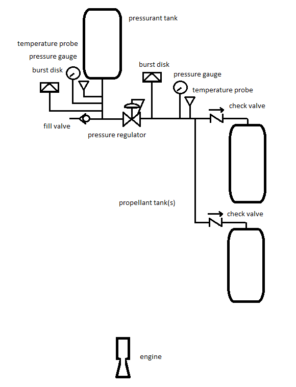
In liquid rocket system designs, burst disks are often placed not only at the pressurant bottle to protect the higher pressure part of the system, but also at the lower pressure end of the regulator which protects the propellant tanks being pressurized. In the event of pressure regulator failure, the burst disk can protect the propellant tank.
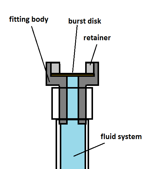
Burst disks are usually in the form of a dead-ended pressure fitting that is adapted to directly connect into the pressure vessel either directly into the pressure vessel volume boundary itself or by a tube connection that is also directly connected into the pressure vessel volume boundary. These fittings have a frangible or breakable membrane that is designed to fail when the pressure reaches a specific design point.
An illustration of the burst disk fitting concept
A burst disk is a “one-time use” device and can not be reset after they have “actuated”. As a pressure relief device, the burst disk is often chosen for its compact size and simplicity. They are in common usage in many industries and can fulfill their relief function very well if they are sized and located properly.
They must be securely and directly connected into the volume of the pressure vessel and have no valves or other hardware which would isolate, block, impinge or constrain the relief function in any way. The American Society of Mechanical Engineers (ASME) Boiler and Pressure Vessel (B&PV) code does have some general advice on this subject and this is a good place to start your study.
These devices are simple to understand but fairly complex to size properly. Beyond the design of the burst disk, you must also consider where these devices will physically fit on your vehicle, where are they located and what is the environment doing around your relief device
The burst disk body and membrane can be subject to corrosion or physical damage that could reduce it’s effective bursting pressure. It’s important to consider the material compatibility of all body, seals and membrane materials that are exposed or “wetted” to the gases inside. Also, its important to avoid getting gouges, nicks or marks on the membrane that would form stress concentrations and weaken the membrane. Even when being cautious, don’t leave your burst disk covered when it needs to be ready to perform. Careful handling is good advice at all points in the project.
There are three things to consider when locating and installing a burst disk: (1) relief (set) pressure, (2) minimum flow rate required, (3) where is your burst disk pointed?
(1) Set pressure of the relief device
Any relief device must be set to actuate (or in the case of a burst disk, to rupture) at a pressure above all of your nominal conditions, but also adequately below any and all failure modes. In some pressure vessel or relief device codes, there are rules of thumb about the set pressure must be a specific percentage (%) above the maximum expected operating pressure (MEOP) or maximum allowable working pressure (MAWP). The thorough examination of all operating conditions and hardware limitations is essential of finding the right set pressure for the relief device.
ASME also has codes for sizing relief valves in process piping, but the rocket industry doesn’t have a particular specification. The aerospace industry does often draft their own specifications and requirements which follow good industrial practices and always include careful design and testing as part of proving the designs to be sufficient.
Another consideration beyond the static pressure in your pressure vessel is the temperature environment of the gases inside. Beyond the fact that higher temperatures from a thermodynamic standpoint create higher pressures, a burst disk relies on the material strength of the membrane and the yield and ultimate strength can weaken under higher temperatures. Some materials (examples are low quality steels) can also become weaker under cold temperatures. Always consider the full range of temperature environments in every application. It’s important to size each burst disk individually and resist the temptation to assume that one device will suit all environments.
There’s a big tolerance on a burst disk set pressure, so be aware of that imprecision. Burst disks are compact but getting a membrane to burst at an exact pressure is not really practical and thus these devices are not very precise. Ask the manufacturer about the expected tolerance on any relief device. It’s also wise to test a few of these devices to measure the actual burst pressure. Make sure you are recording data because failure happens suddenly and you are unlikely to visually see the last pressure reading before burst. If you blink, you can miss the most important data point. Therefore, use a data acquisition system when testing your pressure relief devices.
(2) Minimum flow rate required
Any pressure relief device when activated must be able to drop pressure fast enough to avoid over-pressurizing and failing the pressure vessel. This is a less commonly evaluated situation but its equally important to recognize any scenarios where the transient pressure rise would challenge the relief flow rate needed to keep the pressure below a safe level at all times. Steam pressure systems have this problem and so do cryogenic vessels. Most designers just choose a fitting similar in size to the lines being used, but this isn’t always accurate.
Relief devices are nearly always sized relative to their flow rate afforded. This is sometimes called the “capacity” of the relief valve or burst disk. You’ll need to know your gas and upstream conditions. With this, you’ll need to know the open area when the valve is opened and make this is the smallest restriction in the entire flow path. The open area can be expressed as either the discharge area (Cd A) or the valve coefficient “Cv” value. With each device in each specific location, you must select a burst disk capable of venting enough flow to cover the whole range of expected conditions. This is crucial to finding the right burst disk or relief valve. A device that does not have a large enough capacity will not protect your fluid system.
Another consideration for your relief device is if you have any flow path that is smaller than the area of your relief device. One example of poor design is having your pressure relief device located at the end of a long skinny tube. Even if the open area of the tubing is larger than the pressure relief valve opening, the length of the line can accumulate enough flow friction in the tubing that can unintentionally add up enough pressure drop to pose a significant restriction to your relief flow. This is to say nothing of someone accidentally denting or kinking the tubing which would create a severe blockage of the relief flow. It’s always smart to have your pressure relief device very closely coupled to the pressure vessel volume that you are protecting. This means keeping the distance as short as possible. Always know all of your flow path areas and line lengths!
Another classic mistake in fluid system design is putting a valve or any other restriction device in-between the pressure boundary volume and the pressure relief device that is protecting it. Careful consideration of all valve placements and their positions in all operating modes and under all possible operating scenarios. Put simply: “Do NOT EVER create a situation where the pressure relief device can be isolated or impeded in its operation at any time for any reason, even temporarily. Some piping codes absolutely forbid this. Careful peer-review of your pressure and instrument diagrams (P&ID’s) must look for this situation and avoid it. More than reviewing the paper schematics, one should physically trace all flow paths to be sure the builder hasn’t made such a mistake. The physical hardware must always match the P&ID.
(3) Watch where your burst disk is pointed!
When your burst disk goes off, any foreign object debris (FOD) near the discharging outlet can be thrown out at high speed causing injury or damage to nearby hardware and structures. Even without particulates or FOD, the impinging high-speed sonic jet of gas is very dangerous. No one should be standing near a fluid system while any part of it is pressurized anyway, but you should always consider what might happen when your burst disk goes off. You won’t always know when the device will go off. Be prepared at all times.
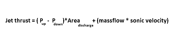
Make sure all hardware is also secure enough to take the sudden thrust from the burst disk relieving itself. This can be a sudden and powerful force that breaks hardware or knocks things over. The rocket thrust equation also applies in this case. To calculate this thrust value, you do this in two parts: (1) You consider the choked flow pressure differential multiplied by the discharge area and (2) add in the product of the mass flow rate of the gas escaping multiplied by the sonic velocity of the upstream gas conditions.
Calculation of the thrust load from a discharging relief device such as a burst disk
As a design note, for nearly all gases, if the upstream pressure is more than double that of the downstream pressure, the flow velocity through any flow path restriction(s) or “orifice area” is sonic or at the speed of sound as computed by the upstream gas pressure and temperature conditions. This is called “choked” flow.
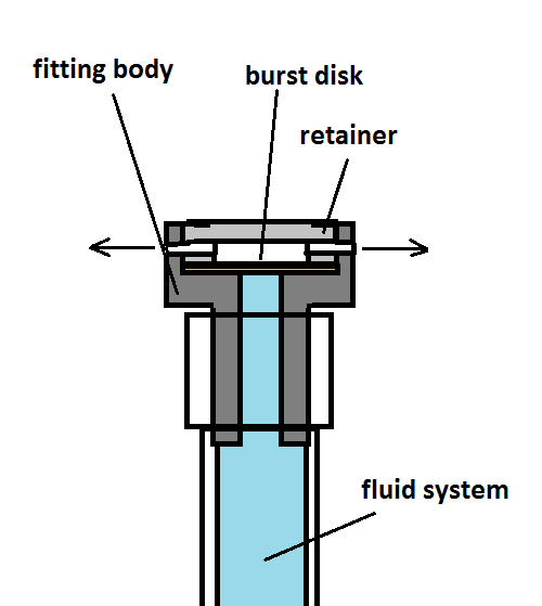
One potential fix to the jet thrust problem out of relief device is to divert and diffuse the discharging outlet flow in opposing or evenly distributed directions as long as the combined discharge flow areas are sufficiently large and balanced.
An illustration of a burst disk device with balanced venting
Another consideration to be made with a burst disk or pressure relief device is to consider the downstream environment where your burst disk is discharging.
Is the relieving gas or gas mixture going to create a flammable or toxic environment? If so, you need to consider how and where you are diverting the hazardous gases being relieved. Some burst disk fittings have threaded ends on both ends which allows the discharging flow to be routed to a safe location, if this is a necessary feature.
Screw-type burst disk fittings made by Zook in three basic types
Are you creating a dangerous environment (reduced oxygen) within a confined space? The subject of confined space safety is very important and worthy of a separate article in itself. Most testing will be done outdoors and in a very well ventilated environment, but the rocket business is full of horror stories of people who have become injured or asphyxiated simply from improper consideration of confined space safety.
A less often considered scenario is whether the space where the burst disk or relief valve is discharging into is fully open to the environment or not. It is possible to overly restrict or “back up” a burst disk or relief valve if the interstage volume in your rocket isn’t very large or isn’t adequately vented to the outside. Sometimes your discharge space simply isn’t big enough. It is very important to know your vehicle hardware geometry very well, measure your volumes and consider all flow areas out of all assemblies.
Find a reputable burst disk manufacturer and distributor
There are a few reputable manufacturers of burst disks. Fike is one that comes to mind, but they tend to be for very large piping sizes used in facility plants. Fike has been providing reliable products for many years to many industries including oil/gas and the aerospace industry. Swagelok has access to a lot of fluid component manufacturers which may be more suitable.
Zook is another manufacturer of burst disk fittings. These in-line devices come as a holder fitting and replaceable disk. The screw-type fittings are two-piece assemblies and have standard pipe thread ends. The disks come in a range of nominal set pressures.
Screw-type burst disk fittings by Zook
zookdisk.com
There are certainly other manufacturers and all of them should be able to provide you with good advice or transfer you to a distributor company to help you with selecting an appropriate device. Before you call or email, you must have already taken the time to understand your pressure environment, capacity and design requirements first. A good component distributor is one that is willing to work with you to find the right part for your application and educate you in making the best choice. Literature is easy to find online and always consider more than one manufacturer to get a good price.
A few last words of caution
Burst disk devices can be manufactured from scratch and other amateur rocketry hobbyists have attempted to do so. This is not a good idea. There are a lot of considerations to make in building a reliable burst disk from scratch not to mention the time and materials to adequately prove the design. To make a burst disk from scratch would become every bit as expensive as simply going to a reputable manufacturer and using their product.
As much as your group may want to save money, pressure relief devices are a critical part of your fluid system to which lives may be at stake. Don’t be cheap. Find a quality manufacturer, select the right product and test them. Ebay is not the place to find quality products.
If anyone has anything to add to this subject, please contact the RRS secretary or the RRS director of research.