EDITOR’S NOTE: This is a continuation of the reporting from the 10-16-2021 flight of the 6-inch rocket design, built and flown by RRS member, Bill Claybaugh.
Post-Flight Motor Inspection
Recovery of the spent motor hardware allowed a detailed disassembly and inspection of the parts. This revealed several useful observations:
Motor Tube
The recovered Motor Tube showed a dent just above the fins that was deep enough to have caused a pressure failure if it had been present while the motor was operating; we thus conclude that the dent occurred during or post impact.
Localized dent in the aluminum case, likely resulting from impact after burnout
Bulkhead
Inspection of the Forward Bulkhead showed it to be in good condition with no evidence of any gas leaks above the two O-rings. The bottom of the Bulkhead showed some damage to the fiberglass heat shield from the ground impact of the rocket but showed plenty of fiberglass heat shield remaining after the about eight second burn. The “nose” of the ignitor assembly remained in place in contrast to previous tests where this part had shattered upon ignition; the change to a steel “gun barrel” liner for the initiator appears to have resolved this issue.
The forward side of the bulkhead showing no leakage or damage.Aft side of the bulkhead showing damage to fiberglass heatshield.
Fins
The four fins were intact and largely undamaged; they appear suitable for reuse in future flight vehicles. Checking with a 0.002” feeler gauge showed there was no gap between the “nose” of any of the fins and the motor tube. A further check using backlighting confirmed that there were no visible gaps between the fins and the motor tube at any location along the fin edges.
Nozzle
The graphite nozzle insert had broken free of its aluminum shell on impact; it was damaged at the exit end and is not suitable for reuse. The aluminum shell showed signs of erosion at the very top of the nozzle. This area was covered by a ring-shaped fiberglass heat shield that was not present upon disassembly. This suggests that the heat shield was fully consumed by hot gas erosion during motor operation; a thicker heat shield is evidently appropriate in future nozzles.
The titanium nozzle extension was undamaged and is suitable for reuse in future nozzles of the same design.
Nozzle was damaged in the impact.
Fin Can
The internal “Fin Can” showed some evidence of blow by of the O-ring that normally sits between the Fin Can and the phenolic liner at the base of the propellant grain. No hot gas erosion was evident in the aluminum structure or in the O-ring, but soot was found on the downstream side of the O-ring. If this O-ring were breeched, hot gas could—in principle—circulate between the liner and the motor wall; thus, this is a potentially significant issue. Mitigating against circulation is the use of high temperature grease between the liner and the motor wall. There was no evidence of any soot or hot gas circulation along the interior of the motor wall. Likewise, there was no evidence of any hot gas leak between the fin can and the motor wall. With minor refurbishment, the fin can does appear suitable for reuse excepting the potential change to two O-rings between the liner and the fin can.
Some “blow by” transient leakage past the seals was evident.Opposite side of the fin can shows same pattern of the “blow by”.
Phenolic Liner
The propellant grain liner was partially consumed at the forward and bottom ends where the liner is exposed to hot gas for the full eight second duration of the burn. There was no evidence of any hot gas contact with the motor tube wall and we thus conclude that the existing liner is of sufficient thickness to handle the current eight second burn time.
Conclusions
Based on this inspection it appears some minor redesign of the nozzle top heat shield is required. It may likewise be prudent to replace the single O-ring used between the internal Fin Can and the phenolic liner with two O-rings. The rest of the vehicle hardware appears to be in good shape and does not seem to require any design changes.
The lack of gap between the fins and the motor wall appears to rule out the possibility of part of the belly-band having become trapped on one of the fins and causing the unexplained turn to the Northeast. The cause of that turn remains https://odellfamilychiro.com/phentermine-37-5-online/ a mystery.
Editor’s Note: This is a reprinting of the original article written by RRS member, Tom Mueller on the subject of pyrotechnic retin-a actuated valves around 1995 (?). He mentions the build of two different rockets (the XLR-50 and the Condor) and a hypergolic rocket he intended to build after this article was written. We hope to gather more photos and details about these rockets and display them in future improvements to this posting. For now, please enjoy the subject matter as the information is very relevant today to amateur builders of liquid rockets. The RRS has been very active lately in re-exploring liquid rockets. The society thought this would be a timely and interesting subject to share with our readers.
For any questions, please contact the RRS secretary, secretary@rrs.org
For an amateur rocketeer seeking to build a liquid rocket, one of the most difficult components to obtain or build are remotely operated valves. A liquid rocket will require at least one valve to start the flow of propellants to the combustion chamber. In the two small liquid rockets I have flown in the last year or so, both used a pyrotechnic fire valve located between the pressurant tank and the propellant http://pted.org/Cytotec.php tanks. The propellants were held in the tanks by burst disks (or equivalent) in the propellant run lines. When the fire valve was actuated, the sudden pressure rise in the propellant tanks blew the burst disks, allowing propellant to flow to the injector. This method of controlling the flow to the rocket allows the use of only one valve, and eliminates liquid valves.
In the case of the first rocket, the XLR-50 which flew in October 1993, elimination of the liquid valve was important because the oxidizer was liquid oxygen, and a small cryogenic compatible valve is very difficult to construct.
For the second rocket, which flew in October 1994, the small size prevented the use of liquid valves. In fact, the single pyro valve I used was barely able to fit in the 1.5 inch rocket diameter. In this article I will describe the design of the valves that were used on these two vehicles, and variations of them that have been used in other rocket applications.
FIGURE 1: XLR-50 pyro-technic “fire” valve
The valve shown in Figure 1 consisted of a stainless steel body with a 0.375 inch diameter piston. The O-rings were Viton (material) and the squib charge was contained in a Delrin plastic cap. The Delrin was used to prevent shorting of the nichrome wire, and also to provide a frangible fuse in case the squib charge proved to be a little too energetic. In practice, I’ve never had the Delrin cap fracture.
The inlet and outlet lines to the tanks were silver brazed to the valve body. The valve was tested many times at inlet pressures of up to 1000 psi without any problems, other than the O-rings would need replaced after several firings due to minor nicks from the ports. To help alleviate this problem, the edges of the ports were rounded to help prevent the O-ring from getting pinched as the piston translates. This was accomplished using a small strip of emery cloth that was secured in a loop in one end of a short length of 0.020-inch stainless steel wire. The other end of the wire was clamped in a pin vise which in turn was chucked in a hand drill. As the wire was rotated by the drill, the emery was pulled snugly into the port, where it deformed into the shape of the inlet, and rounded the sharp edge. I used WD-40 as a lubricant for this operation, allowing the emery to wear out until it would finally pull through the port. I repeated this process a few times for each port until the piston would slide through the bore without the O-rings snagging the ports.
Another requirement is to lubricate the O-rings with a little Krytox grease. This helps the piston move freely and greatly reduces the problem of nicked O-rings.
FIGURE 2: Fire valve for a micro-rocket
The pyro valve I used in the 25 lbf thrust micro-rocket that was launched in October of 1994 is shown in Figure 2. This valve was identical in operation to the XLR-50 valve, with the major difference being its integration into the vehicle body. The valve body was a 1.5 inch diameter aluminum bulkhead that separated the nitrogen pressurant tank and the oxidizer tank. Because of the very small diameter of the rocket, the clearances between ports and O-rings were minimized, just allowing the valve to fit. The fuel outlet port was located at the vehicle center, providing pressure to the fuel tank by the central stand pipe that passed axially down the oxidizer tank. The piston stop was a piece of heat-treated alloy steel that was attached to the valve body by a screw. This stop was originally made from aluminum, but was bent by the impact of the piston in initial tests of the valve. The black powder charge in the Delrin (https://openoralhealth.org/prednisone/) cap was reduced and the black powder was changed from FFFg grade to a courser FFg powder, but the problem persisted. The stop was re-made from oil hardening steel and the problem was solved. In this application, the port diameters were only 1/16 inch so only a small amount of rounding was required to prevent the O-rings from getting pinched in the ports. The valve operated with a nitrogen lock-up pressure of 1000 psi.
FIGURE 3: Fire valve for Mark Ventura’s peroxide rocket
A more challenging application of the same basic valve design was used for the fire valve of Mark Ventura’s peroxide hybrid, as shown in Figure 3. This was the first application of this valve where liquid was the fluid being controlled, rather than gas. In this case the liquid was 85% hydrogen peroxide. The second difficulty was the fact that the ports were required to be 0.20 inch in diameter in order to handle the required flow rate. The valve was somewhat simpler than the previous valves in that only a single inlet and outlet were required. The valve body was made from a piece of 1.5-inch diameter 6061 aluminum, in which a 1/2-inch piston bore was drilled. The piston was also 6061 with Viton O-rings, which are peroxide compatible. The ports were 1/4-inch NPT pipe threads tapped into the aluminum body. The excess material on the sides of the valve was milled off, so that the valve was only about 3/4 of an inch thick, and weighed only 4 ounces. Even though the piston size was 1/2 inch, the same charge volume used in the 3/8 inch valves was sufficient to actuate the piston.
In testing the valve with water at a lock-up pressure of 800 psi, I was pleased to find that even with the large ports, O-ring pinching was not a problem. One saving factor was that the larger size of the ports made it easier to round the entrances on the bore side. The valve was tested with water several times successfully before giving it to Mark for the static test of his hybrid.
The only problem that occurred during the static test of hybrid rocket was that the leads to the nichrome wire kept shorting against the valve body. Three attempts were made before the squib was finally ignited and the engine ran beautifully. I have since been able to solve this problem by soldering insulated 32-gauge copper wire to the nichrome wire leads inside the Delrin cap. In this way, I can provide long leads to the valve with reliable ignition.
My next liquid rocket is a 650 lbf design that burns LOX and propane at 500 psia. This engine uses a Condor ablative chamber obtained from a surplus yard. For this reason, I call it the Condor rocket. This rocket uses a scuba tank with 3000 psi helium for the pressurant. I decided to build a high pressure version of my valve as the helium isolation valve for this rocket. When firing this rocket, just prior to the 10 second count, this valve will be fired, pressurizing the propellant tanks to 600 psi. I assumed going in to this design that the O-rings slipping past a port simply wasn’t going to work at 3000 psi.
At these pressures, the O-ring would extrude into the port. In order to get around this problem I came up with the design shown in Figure 4.
FIGURE 4: High pressure helium valve for Condor rocket
For this valve, the O-ring groves were moved from the piston to the cylinder bore of the valve body, so the O-rings do not move relative to the ports. The piston is made from stainless steel with a smooth surface finish and generous radii on all of the corners. The clearance between the piston and the bore was kept very small to prevent extrusion of the O-rings. The valve operation is similar to the one shown in Figure 3, and the valve body is made in the same way except female AN ports were used rather than NPT ports. When the valve is fired, the piston travels from the position shown in Figure 4a to that shown in Figure 4b. During this travel, the inlet pressure on the second O-ring will cause it to “blow out” as the piston major diameter translates past the O-ring groove. The O-ring is retained around the piston, causing no obstruction or other problems. This valve has been tested at 2400 psi inlet pressure with helium and works fine. It will be tested at 3000 psi prior to the first hot fire tests of the Condor rocket next spring.
As a side note, essentially an identical valve design as the one used on the Condor and Mark’s valve is a design shown in NASA publication SP-8080, “Liquid Rocket Pressure Regulators, Relief Valves, Check Valves, Burst Disks and Explosive Valves”.
A second pyro valve is used on the Condor system as shown in Figure 5. This valve is used to vent the LOX tank in the event of a failure to open the fire valve to the engine.
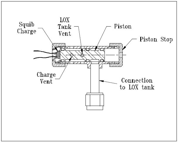
FIGURE 5: Emergency vent valve for LOX tank, Condor rocket
When the propellant tanks are pressurized by the helium pyro valve, the LOX tank auto vent valve (shown in Figure 6) closes. If the engine is not fired after a reasonable amount of time, the LOX will warm up, building pressure until something gives (probably the LOX tank). The pyro valve shown in Figure 5 is used as the emergency tank vent if the engine cannot be fired. The valve body is stainless steel with a stainless tube stub welded on for connection to the LOX tank. This valve has been tested to 800 psi with helium and works fine. In this case, some ‘nicking’ of the O-rings can be tolerated because the O-rings are not required to seal after the valve is fired. The ports in the bore are still rounded, however, to prevent the O-rings from getting nicked or pinched during assembly of the valve.
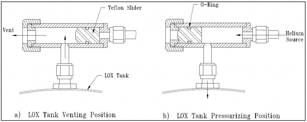
Even though it is not a pyro valve, I have shown the LOX auto-vent valve in Figure 6 because this design has proven to be very useful for venting cryogenic propellant tanks without requiring a separately actuated valve or control circuit. The valve uses a Teflon slider that is kept in the vent position as shown in Figure 6a.
This allows the tank to vent to the atmosphere, keeping the propellant at its normal boiling point. When the helium system is activated, the pressurant pushes the slider closed against the vent port, sealing off the LOX tank, as shown in Figure 6b. An O-ring is used around the slider to give it a friction fit so the aspiration of the LOX tank does not “suck” the slider to the closed position. This problem happened to David Crisalli (fellow RRS member) when he scaled this design up for use on his 1000 lbf rocket system. I have used this design on the LOX tank of my XLR-50 rocket, which used a 1/4-inch diameter slider, and on the Condor LOX tank, which uses a 1/2 inch slider. In both cases the vent valve worked perfectly.
FIGURE 6: Automatic LOX tank vent valve
The main fire valve on the Condor rocket is a pair of ball valves that are chained together to a single lever so that both the fuel and oxidizer can be actuated simultaneously for smooth engine startup. For static testing of the rocket, I will use a double-acting air cylinder to actuate the valves. For flight, however, I plan to use a pin that is removed by an explosive squib to hold the valve in the closed position. When the squib is ignited, the pin is pulled by the action of the charge on a piston, allowing the valves to be pulled to the open position by a spring. This method may not be very elegant, but it is simple, light, and packages well on the vehicle. David Crisalli has successfully employed this technique on his large rocket.
That covers the extent of the pyro valves I have built or plan to build so far. In the next newsletter, I will present the design and flight of the small hypergolic propellant rocket that used the valve shown in Figure 2.