How to Make 4-20 mA Current Loop Measurements

by Roger Lockhart of DATAQ Instruments

originally published 9/30/2013, reprinted with permission


It seems that at least one 4-20 milliamp (mA) measurement is required by our typical customer, and the way to do it is a constant source of confusion for many.  So I thought I’d zero in on the various 4-20 mA current loop configurations and elaborate on the specifics you need to know to make a successful measurement.  The following is ordered from the most to least common configuration, and I hope to cover all those that I encountered in customer applications.  If yours isn’t included, please contact DATAQ technical support.

dataq.com

4-20 mA Current Loop Basics

Sensors or other devices with a 4-20 mA current loop output are extremely common in industrial measurement and control applications. They are easy to deploy, have wide power supply requirements, generate a low noise output, and can be transmitted without loss over great distances. We encounter them all the time in both process control and basic measurement data logger and data acquisition applications.

The idea behind 4-20 mA current loop operation is that the sensor draws current from its power source in direct proportion to the mechanical property it measures. Take the example of a 100 psi sensor with a current loop output. With 0 psi applied, the sensor draws 4 mA from its power source. With 100 psi applied the sensor draws 20 mA. At 50 psi the sensor draws 12 mA and so on. The relationship of mechanical property measurement to current output is almost always linear, allowing the resulting current loop data to be scaled with a simple mx+b formula to reveal more useful measurements scaled into engineering units.

How you actually measure the 4-20 mA current loop signal is a function of the sensor’s architecture and the capabilities of the instrument you’ll use for the measurement.

Terminology

So that my discussion translates well across the various kinds of 4-20 mA current loop configurations, I’ve opted to standardize the terminology I use to describe each. Here’s an overview:

“E” (DC excitation)

Most configurations that follow will show a DC voltage excitation source that I denote as “E”. Many who use current loop sensors for the first time are surprised to learn that they need to supply this excitation source. Nonetheless, unless the sensor is self-powered (i.e. AC line powered) an external dc source is required. The good news is that this can sometimes be supplied by the instrument, and the range of acceptable supplied voltage values is usually very wide, typically 10 to 24 VDC.

“R” (shunt resistor)

Here’s a bit of trivia for you:

No instruments measure current directly.

They all do it indirectly by measuring the voltage dropped across a resistor of known value, and then they use Ohm’s Law to calculate actual current. The resistor is referred to as a “shunt”, is absolutely required to make a current measurement, and is either supplied externally to, or built into the measuring instrument. For clarity, I assume that it’s supplied externally.

“i” (current loop value ranging from 4 to 20 mA)

This is the 4 to 20 mA current signal generated by the sensor. Note that some sensors may draw 0 to 20 mA and even other values, but the vast majority of them use the 4 to 20 mA convention.

“v” (shunt voltage that’s proportional to current)

This is the voltage drop across the shunt that is actually measured by the instrument. Since our industry has standardized on a shunt value of 250 Ohms, “v” will range between 1 and 5 volts for a 4-20 mA current loop signal.
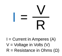
Note that shunt resistor value is arbitrary as long as it’s a known (fixed) value. You also need to ensure that it doesn’t burden the loop, so lower values are better than higher.

Yes, I mean lower.

Remember that we’re working with current, not voltage, so the rules are inverted. Just as infinitely-high resistor loads work well for a voltage source, you can take the load all the way to zero Ohms for a current source without consequence.

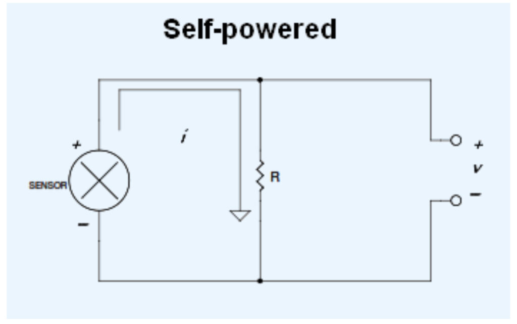
 Self-Powered Sensors (Most Common)

I promised to order these configurations from most to least common, and the self-powered sensor just noses out the first runner up. Self-powered sensors are those that, well, power themselves. The sensor may have an integral ac power supply, thereby negating the need for an external DC power source.

Or it may not be a sensor at all. It could be an output from a Programmable Logic Controller (PLC) or other source that is internally powered.

2-wire Sensors (Low-side Shunt)

Okay, this can get confusing for first-time  4-20 mA current loop users.

Yes, it is possible to both power the sensor and measure the current it draws over the same two wires. In the 2-wire examples shown here, only two wires connect the sensor to its power supply, and the sensor draws current from it in direct proportion to the mechanical property that it measures. As current changes, the voltage developed across resistor “R” will change, thus providing a signal that’s suitable to connect to a measuring instrument like a data logger or data acquisition system.

In most situations, care should be taken to place the resistor in the low-side of the loop as shown here, as opposed to the high-side. Doing so will allow non-isolated instruments to make the measurement. In the next section, I’ll deal with a high-side shunt placement and discuss these cautions in more detail.

2-wire Sensors (High-side Shunt)

This configuration is almost exactly like the low-side, 2-wire approach, but it places the shunt resistor in the high-side of the loop. Note that while the voltage across the resistor is proportional to the current drawn by the sensor (just like the low-side approach), there is also a common mode voltage (CMV) present on either side to ground. On one side to ground the CMV is equal to the supply voltage. On the other side to ground it’s equal to the supply voltage, less the voltage dropped by the resistor (v).

The presence of the CMVs places conditions on the instrument that you use to measure v. Specially, the instrument needs to have an isolated front end so it can float to the level of the CMV and still successfully make the measurement. Try this with a non-isolated, single-ended instrument and you will short-circuit the sensor to ground. A non-isolated differential instrument will either saturate or provide erroneous results.

3-wire Sensors

Three-wire sensors with a process current output have a separate wire for ground, signal (4-20 mA), and the power supply. This configuration is the easiest for current loop beginners to grasp, one input for power and a second for the current loop with a common ground. The primary advantage of a 3-wire sensor over its 2-wire counterpart is its ability to drive higher resistive loads. Resistors drop voltage for any given current in direct proportion to their resistance value. Holding current constant, higher resistances drop more voltage. Turning back to the 2-wire sensor and holding current constant, as the shunt resistance increases the voltage drop across it also increases. You might reach a point where the voltage dropped by the shunt lowers the voltage drop across the sensor below the minimum required for it to operate properly.

We had a customer whose 2-wire current loop measurements functioned beautifully until loop current reached about 18 mA, at which point everything went haywire. Upon close examination, we determined that the supply voltage she used was too low by at least 0.56 volts. She needed 2 mA more measurement to reach full scale, which translates to 0.56 V with her 250-Ohm resistor. The solution was to use a higher voltage power supply to ensure that the voltage drop across the sensor stayed above the minimum level. She could have also used a 3-wire sensor, which ensures that the voltage applied to the sensor is independent of shunt resistor voltage drop.

Watch Your Grounds (or use an isolated instrument)

Contrary to what many believe (and have been erroneously taught in school), grounds are almost never the same in industrial settings, exactly where most 4-20 mA current loop sensors are used.

Two or more grounds that are the same means that they are at the same potential. If so, a measurement between the grounds of the various field sensors and the instrument using a digital volt meter (DVM) on both its DC and AC settings will show zero volts, or very close to it.

In reality, you’ll measure at least several volts, and I’ve seen as much as 75 Volts. When grounds that are not at the same potential are tied together (which you need to do to make a measurement), current flows through them, creating several possible measurement outcomes for non-isolated instruments:

  1. The measurement is noisy.
  2. The measurement is inaccurate.
  3. You irreparably damage the instrument.
  4. You saturate the instrument (it’s not damaged, but you can’t make a successful measurement, either.)

To remedy these problems requires the following:

  1. Use an isolated instrument for your 4-20 mA current loop measurements. This single decision allows you to ignore all other grounding issues in exchange for successful measurements in any situation. If you don’t have an isolated instrument, read on…
  2. Ensure that the loop power source is isolated. This means that its output ground (the one connected to the sensor) is not tied to its input ground (the one that connects to AC line power.) An isolated power source means that the output ground can be tied to another ground (like a non-isolated instrument) without consequence.
  3. If using self-powered sensors, ensure that the low-side of the loop is isolated from its power source.
  4. If using sensors that require an external dc power source, ensure that the shunt resistor is placed in the low side of the loop (see “2-wire Sensors (Low-side Shunt)” above.)
  5. If you lack control over the power sources and determine that they are not isolated, then your only option is to power ALL devices (power supplies, self-powered sensors, the instrument, and its connected PC) from exactly the same power outlet. Don’t make the mistake of using outlets that are close to each other. If you run out of receptacles on a single outlet, then use a power strip.

Again, it’s worth repeating that all of the cautions associated with proper grounding disappear if an isolated instrument is used to make the measurement.

Sensors with 4-20 mA outputs are encountered in all disciplines and in many configurations.

Contact DATAQ with any questions that arise in your unique situation.

dataq.com


This article has been reprinted with permission from DATAQ Instruments, a manufacturer of quality data acquisition and data logger products used by many professionals and amateur rocketry hobbyists.  

The RRS is thankful to DATAQ for their assistance.

Also, you can watch DATAQ YouTube instructional videos on this and other subjects.

For information on DATAQ products, go to their website: 

www.dataq.com


October 2018 meeting

The RRS met for our monthly meeting on Friday, October 12, 2018, at the Ken Nakaoka Community Center in Gardena. As usual, we got started by calling the meeting to order and reading the treasury report. We had a big agenda but covered most of the topics.

[X1]
Richard Garcia wasn’t able to join us at the October meeting. He wanted to report that he has made some design improvements to the RRS standard liquid rocket. He’s finished upgrading his engine design code to be able to analyze a blowdown engine (pressure-fed from the tanks). He also will soon have drawings for a thrust chamber design.

With some luck, I hope he’ll be back into testing at the MTA sometime soon next year.

[X2]
Electro Tech Machining (ETM) in Long Beach, California, specializes in graphite stock, graphite parts and Electrical Discharge Machining (EDM). They are experts and have been a loyal supporter of amateur rocketry groups such as UCLA and USC. The Reaction Research Society is happy to endorse them as they have been a great support to our society member’s projects as well.

Electro Tech Machining – Long Beach, contact information

Contact Cathy Braunsdorf at Electro Tech Machining.

Electro Tech Machining
2000 W. Gaylord Avenue
Long Beach, CA, 90813
(562) 436-9281

Electro Tech Machining in Long Beach, the graphite specialists

Electrical Discharge Machining (EDM) – Wikipedia article

I stopped in this week to pick up some round stock for making more graphite nozzle pucks for the ballastic evaluation motor (BEM) that is nearing completion. Graphite makes an excellent high temperature material for nozzle throats or any low ablation surfaces. We have used graphite inserts into reclaimed alpha and beta nozzles over the years at the RRS. Our society members have used graphite throats in their larger solid motor tested at the RRS MTA back in June 2018.

Plastic nozzle puck used for scale against the graphite round stock acquired by the RRS from Electro Tech Machining in Long Beach, CA

Moving into the meeting agenda, we shifted the order a little, but I have kept the numbering the same:

[1]
The latest educational event at Weigand Elementary school in Watts is going very well. The LAPD CSP program continues to help sponsor the event and we get great excitement from the kids. This Friday was the fifth of six educational events where they get to assemble the empty rockets. Osvaldo, Larry and Frank were on hand to help with the build process. The kids are really enjoying the process of learning and painting the team rockets will done in the last session before going out to launch at the RRS’s private testing site, the Mojave Test Area (MTA).

Two of our young participants show their assembled RRS alpha rocket at Weigand Elementary, Frank Miuccio in the background at the right

[2]
The next launch event at the RRS MTA will be the final step in the RRS’s educational program for Weigand Elementary school. We have this scheduled for October 27th and we hope to have cooler weather than in prior events now that the summer has passed. We have nine alphas from Weigand Elementary and three more alphas from our new membership, Wilbur Owens, Xavier Marshall and Michael Lunny.

Xavier Marshall looks over his first RRS alpha, welcome to the club!

[3]
I gave my quarterly briefing on the SuperDosa project at the October meeting. This time, I organized my thoughts and ideas into a presentation to give the RRS a general overview of the project and where we are so far.

Largely, I wanted to reiterate the project’s overall goals to many of the new members who have joined the RRS since the project’s inception in January 2017. The RRS intends to retake the amateur rocketry altitude record and in the process reopen our ability to make larger solid rocket motors and expand our reach both in our own community and literally with payloads ultimately flying above the atmosphere.

SuperDosa quarterly report, Oct-2018

I also acknowledged the recent progress of some of our new members formerly of the Chaminade Rocketry Club. Also, USC had a launch attempt with their Traveller III rocket, part of their Spaceshot Initiative. Unfortunately, instrumentation was not functioning but the flight looked to be nearly perfect. I hope USC will come present their recent accomplishments at a future RRS meeting.

Materials acquisition and some discussion about how to proceed with the propellant burn rate testing were the highlights of the discussion. More progress needs to be made in a few areas for completing the first prototype:

(a) Complete the design of all parts for the first prototype (6-inch booster)

(b) Begin prototyping instrumented dart payloads to practice flying and recovering these while getting good data. Making these devices work under the tight and unforgiving conditions that they must.

(c) More work in parachute recovery

(d) Estimating friction heat loads and heat mitigation strategies for the payload

Much of this prototyping work can be done at the MTA by flying smaller subscale vehicles and testing subsystems to prove they can work. More importantly, these tests give the society practice for the large vehicle testing which will reclaim the altitude record for the RRS.

The response to the SuperDosa project’s progress was very constructive and many new ideas were offered. I’m thankful to Frank, Steve Majdali, Larry, Osvaldo, Bill Behenna, Drew and Xavier for their inputs. I have taken notes and given actions to other members who are willing to help advance key areas of the project. Unfortunately, this topic was to be the last of the evening as my presentation easily exceeded the 20 minutes I intended.

The next quarterly report for the SuperDosa project will be January 11, 2019, and I hope to report a great deal of progress.

[4]
We had a last minute addition to the agenda, with Steve Majdali talking about black powder rockets and some very nice black powder rocket making tools he acquired while on travel. Black powder rockets are a classic form of amateur rocketry and involve many techniques that are broadly useful in other areas such as composite grain motors.

Steve Majdali shows the RRS his metal spindle for a cored grain type of 3-inch black powder rocket

Steve gave us a lot of great information specific to black powder making, pressing and a wealth of other practical information. Based on this new avenue of research, I felt the RRS would benefit more if Steve discussed this topic in more length in a stand-alone article soon to be published here on the RRS.ORG website.

[5]
The RRS has been in contact with the Additive Rocket Corporation (ARC) of San Diego. They are a startup company in San Diego with the goal of making high performance rocket motors using their novel design methodologies and 3D metal printing equipment. Discussions are still underway and thus there wasn’t much to tell. ARC was an exhibitor at the 75th anniversary symposium this year in April.

Additive Rocket Corporation (ARC) of San Diego at the 75th anniversary RRS symposium

[6]
In my discussions with ARC, they were kind enough to offer to 3D print a simple small liquid rocket chamber I designed. Prices are not cheap, but this futuristic manufacturing technique offers a great deal of complexity that is not easily nor cheaply replicated by traditional means. I have been in discussions with ARC and hope to have more to present at the next RRS meeting.

125 lbf thrust chamber design, uncooled; prototype for the RRS standard liquid project

[7]
Alastair Martin could not join us at October’s meeting. I was going to have him discuss the current topics of interest at the recent 21st Annual Mars Society Convention held this summer. Alastair is very involved with the Mars Society and the RRS.

Alastair will be at the November RRS meeting so we’ll put this topic on the next agenda.

[8]
New RRS members, Wilbur Owens and Xavier Marshall, are active with the Experimental Aircraft Association, chapter #96, at the Compton Airport in the Los Angeles area. EAA-96 is a like-minded group of enthusiasts centered on experimental aircraft. The EAA-96 has hangar space and a range of machining tools offered to their members.

Experimental Aircraft Association, Spirit of 96

Xavier had mentioned at the last meeting that the EAA would love to host a visit by the RRS. Accepting the EAA’s invitation, the RRS has scheduled a visit to the EAA in Compton on November 3rd at 10:00AM. The EAA will give an hour tour of their facilities and projects. We hope to foster a strong relationship between the EAA and the RRS.

Talk with Xavier Marshall, Wilbur Owens, the RRS president, vice president or secretary for details.

Experimental Aircraft Association (EAA) hangar
1017 W. Alondra Blvd.
Compton, CA, 90220
(310) 612-2751

One of the key points of discussion at this visit will be to discuss how the RRS and EAA can help each other or participant in joint projects. The RRS is interested in using the EAA hangar facilities if they are available. Annual membership at the EAA is $40 to the EAA national society and $40 more to the local chapter at the Compton Airport. As I understand but must confirm, with EAA-96 chapter membership, RRS membership can have access to the machining tools for building rocketry parts for those of us without facilities in our own homes.

Xavier had also mentioned that hangar storage was often very cost-effective which could be a service that the RRS could use as we look to expand our shop capabilities to our membership.

EAA Chapter 96 hangar, Compton Airport

The EAA hangar is just straight east and not very far from our regular meeting location in Gardena at the Ken Nakaoka Community Center just north of Artesia Blvd. (CA-Hwy 91). The address is above.

[9]
Osvaldo’s recent successful design of an alpha parachute recovery system was not able to be covered. We may expand this topic into a fully illustrated RRS.ORG article if we can not get this topic on next month’s agenda. This has been a quiet success and definitely worthy of exhibition to our membership.

[10]
Jerry Fuller of Aerospace Corporation had indicated interest in building and testing a larger subscale prototype of his liquid-infused hybrid motor grain. Aerospace had earlier this year successfully demonstrated a smaller prototype in flight at the RRS MTA. In choosing the next larger design, he has selected a common model rocketry size (98 mm) just under 4-inches which will allow him to use commercially available rocket body parts. Jerry is active with our friends at Rocketry Organization of California (ROC).

At this time, he is still working on the design until resources can be allocated. The RRS has invited him to present his results and the new prototype he has in mind. The RRS is happy to support private groups with a testing area and a community of amateur enthusiasts happy to assist.

[11]
The RRS had discussed having a small group of our membership go out to the next ROC event which is held the 2nd Saturday of the month. Unfortunately, neither I nor Drew were able to go this month. With the Friday night rains falling on the city, it might not bode well for the event at the Lucerne Valley as they must operate on the dry lake bed.

We are looking to coming out to the November ROC event in the Lucerne Valley and hope we can bring other RRS memmbers with us. In particular, some of our members are interested in getting more practical experience through the NAR or Tripoli prefect at ROC. Moreover, some of the RRS membership is seeking experience and support as we acquire letters of recommendation for the California pyro-op licensing in rocketry.

[12]
Saturday seminars have not yet been scheduled, but the RRS is still committed to offering an extended time period for fuller discussions by invited speakers.

[+] RRS member, Jim French, is a speaker of which we would be very excited to have. Jim was a development engineer at the famed Santa Susanna Field Laboratory here in Los Angeles during the development of the reliable and powerful H-1 engine and the injector for the massive F-1 engine. Later, he worked at TRW on the reliable, hypergolic fueled, Apollo Descent engine at TRW at their San Juan Capistrano testing site (now defunct). His book, “Firing a Rocket Engine” is available on Amazon and it is a great read.

Amazon.com – James A. French, Firing a Rocket Engine

[+] Reaction Research Society founder, George James, is another speaker we have been wanting to have. His founding work with his other organization, the Rocket Research Institute (RRI) was a great topic he covered only briefly at the 75th anniversary symposium in April.

[+] Rocketdyne retiree and materials expert, John Halczuk, is another potential speaker on the subject of his extensive research of the V-2 rocket. He gave an excellent talk last year at California State University in Northridge, on history of the V-2’s development and deployment. The V-2 guided many design decisions still used in modern rocketry today in both the United States and particularly in the former Soviet Union.

We were not able to discuss this topic in detail, but more information will be forthcoming, hopefully in the form of an announcement of our first Saturday seminar at the Ken Nakaoka Community Center on a Saturday morning.

[13]
The next RRS symposium date in 2019 will be set soon. Based on the powerful success of the 2018 event, the RRS has decided to further the tradition one more year. We hope to have an even better mixture of universities, private companies and government agencies.

Date to be announced in November, the RRS will hold the 2019 symposium at the Ken Nakaoka Community Center in Gardena

There was no time to formally raise the subject, but it was decided by the council members present at the October meeting that the 2019 RRS symposium date will be formally set by an offline discussion and the date officially announced at the next RRS meeting on November 9, 2018.

[IN CLOSING]
The next meeting of the RRS will be November 9th at the Ken Nakaoka Community Center in Gardena.

We will most certainly discuss the results of the MTA launch event scheduled for Saturday, October 27, 2018. I will build the agenda starting at the end of the month. Please contact the RRS secretary for ideas and information on meeting topics.

secretary@rrs.org

As per our constitution, the RRS will hold its annual nominations of officers for the next calendar year 2019 at the November 9, 2018 meeting. Voting by the administrative membership will take place thereafter and managed by our election chairman. Results will be announced at the next meeting on December 14, 2018.

Thank you for reading.

—- —-