
by Dave Nordling, RRS.ORG
On July 25, 2020, the Reaction Research Society held its first launch event at the RRS MTA since the start of the pandemic. Our pyrotechnic operator in charge that day was our society president, Osvaldo Tarditti. I was his backup. We also had Jim Gross come out for the event who has been our pyro-op in charge at many of these events.
We observed social distancing as best as we could and everyone was wearing a mask. Protective equipment is normally required for loading operations and keeping our people spread apart only makes good sense. The heat (107 F) was significant but everyone was largely prepared to endure the exhausting environment. We had a few glitches in the launch process which can happen at any event. It is times like these that make patience and planning very valuable.
We held a short safety briefing before beginning launch operations. I reviewed the natural and man-made hazards at the MTA, underscored the importance of hydration, the buddy system and montioring each other and ourselves for hest exhaustion. We had a lower turnout as this was a private society event and with the heat we sought to run through the micrograin launches in one straight series holding the hybrid rocket flight for last. After the safety briefing, Larry performed a propellant burn demonstrstion then we adjourned to the observation bunker while the pyro-op’s began to ready the micrograin rockets in the rack. John Krell assisted me with the rack loading and arming process.
We had four micrograin rockets and the hybrid rocket for this launch event. There were three alpha rockets with slight differences in their design. John Krell had built three avionics payloads, one for each, to capture the trajectory data (acceleration and barometric pressure) so that an apt comparison could be made. We also had an avionics package and recovery sytem (parachute) built into the beta by Jerremy Hoffing, son of Larry Hoffing. The hybrid rocket would be last in the series,

Bill Inman came to the launch event to both spectate the launch of the micrograin and hybrid rockets and also examine portions of his launch rail unit from his Scalded Cat steam rocket project. He has already begun planning a newer steam rocket design.

THREE ALPHAS
This segment talks about the three alphas we built and flew to compare two design changes. The three designs were:
- standard alpha with three-foot propellant tube, plain carbon steel nozzle
- standard alpha with three-foot propellant tube. ceramic coated nozzle
- longer alpha with four-foot propellant tube, ceramic coated nozzle
Among these three designs, we were examining the effect of the ceramic coated nozzles which used a proprietary coating process used on automotive engine pistons and exhaust pipe interiors in the racing industry. Specialized Coatings was the company providing the service which we have used before. The coating was proven in a prior alpha flight in 2017, but the nozzle was misplaced and lost after photos were taken at the event. A repeat test was warranted to not only provide photographic evidence but also to cut-up a nozzle to see how the coating survived. It is likely that a ceramic coated nozzle can survive multiple firings before erosion sets in.


The other variable explored was to change the length of the propellant tube and thus increasing the propellant available. Past projects have explored using longer propellant tubes, but this project would bring flight data for direct comparison. To achieve maximum altitude, a second ceramic coated nozzle was used. Just based on the time of flight observed from the observation bunker, the four foot alpha remained aloft for at least four more seconds. John Krell took some video like a few others did. We may be able to estimate the trajectories if we fail to recover the data from one or all of the alphas.


BETA WITH RECOVERY SYSTEM
The beta rocket used at the launch event had a recovered nozzle which had some minor erosion. This was sufficient for this flight. The two features were the parachute recovery system and the avionics package to record altitude data.

The beta was the first micrograin rocket ready for flight and thus it was loaded into the box rails built for the beta. This beta design differed from the standard design by having a straight coupler meaning that the aluminum payload tube was the 2.0-inch diameter as the 2.0-inch DOM steel propellant tube. Because of cost, betas are produced in smaller and less frequent batches. This sometimes leads to more variations in the design. With a little more part production, we can achieve greater consistency between betas.

The typical aluminum coupler design flares out to a 2.5-inch aluminum payload tube. The standard design better fits the box rail launcher which was made with a 2.5-inch bore. The standard payload tube size would have offered more room for packaging the recovery system. Nonetheless, Jeremy was able to fit everything together and the beta propellant tube was filled and made ready.
The 2.0-inch rocket did lay properly inside of the quad-rail launcher, but the sloppy fit was a little concerning. We had considered using a sabot to fill in the gap, but no practical solution could be made. The solid steel rails would contain the rocket but the concern was whether the avionics switch would get bumped into the off-position. To avoid this, a small block of wood was used to lift the beta high enough to clear the switch near the top of the payload.

The first launch attempts resulted in no firing. After re-checking the cabling and my hookups, no error was found. Second attempt also had the same negative result. To expedite the launch process we proceeded with the alpha launches.


After the alphas flew, we re-tried the beta rocket with a dual-igniter for redundancy, the first electric match was found to be defective. This time after some initial trouble with the battery, on the third attempt we got ignition.

SECOND FLIGHT OF THE HYBRID ROCKET
A new rocket body was built to hold the same Contrails H222 nitrous oxide hybrid motor flown earlier. this year. Larry Hoffing did a lot of work building a new rocket body from scratch. It’s boat tail was fitted to accept the 16-inch long, 38mm casing of the Contrails H222 model. Osvaldo built in the parachute recovery system and all parts of the rocket fit well together at the RRS MTA. I changed the location of the vent tube and routed the line to the outside trimming the excess away once the rocket was vertical and captured in the 1010 rail. A lot of this preparation was documented on the RRS Instagram page.


The Contrails H222 motor is a very simple design made for reloading and re-use. The designs are built to common metric standards used in model rocketry. Using the smallest size, 38mm, for a first hybrid project made sense as we would learn the practical things necessary for a successful launch. It also was a size very close to the micrograin rockets that the RRS commonly uses.

The Contrails design is very simple and easy to assemble with the right tools and lubricants. The interior of the 16-inch long motor is divided into two parts, one for filling with nitrous oxide liquid supplied under pressure and the other holds the inert plastic reloadable fuel propellant grains and a graphite nozzle. The two volumes are separated by a dual O-ring sealed piston called the floating injector.
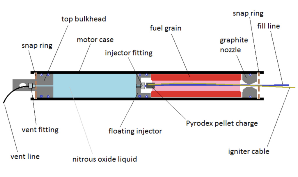
The motor uses a snap-ring retention method for securing the graphite nozzle plug in the aft and another snap ring is used to keep the vented top plug in place. The internal pressure of the nitrous oxide liquid holds the floating injector down against the fuel grain. The injector consists of a stainless steel Parker push-to-connect plastic tube fitting. The ignier is designed to break the filling line inside of the motor releasing the flow of nitrous oxide and providing ignition nergy to start the combustion of the plastic fuel grain in the presence of newly streaming oxidizer flow. It is a very simple and impressive system. Contrails also sells kits and replacement parts to replace those that wear out.

Last launch attempt successfully demonstrated the motor assembly, motor integration into our first rocket body and loading process. The remote actuation of the nitrous filling line and separate electric ignition circuit required a two-channel firing rig which operated well as expected. The flaw in the first aunch was failing to quickly and cleanly sever the thick-walled nylon fill line.

The nitrous bottle was recharged with liquid and secured to an I-beam. The valve manifold was attached and after a quick tightening was free of leaks. We secured the electrical and fluid connections to the rocket and ran our control lines back to the old blockhouse with all of our observers in the safety of the observation bunker. Osvaldo and I conducted all operations with care. Then the first problem struck.

We couldn’t get the fill solenoid to open. This was first thought to be the battery. In past summer events the heat can degrade the battery. We had several no-fire conditions which led us to suspect the battery health. For the beta, the fault was a broken lead on the electric match. Running a voltmeter showed a little weakness of the battery but 12-volts was showing on the needle. We moved one of the cars closer to the blockhouse to use its battery but the solenoid still wouldn’t open. Given, the late hour in the peak of the afternoon, we scrubbed the launch attempt and safed and disconnected the fluid and electrical system.

The bottle pressure was reading very high that day and although the vessel and plumbing is amply rated for the 1400 psi reading on the gauge. By weight, the bottle wasn’t overfilled, but the heat of the day certainly brought the pressure up. The solenoid valve was bought as part of an assembly sold by a different supplier. With no labelling or marking on the solenoid, there is nothing to identify the manufacturer or model number. A couple emails were sent to the seller but no information on the valve make and model has been given. The internal design and operating limitations of this 12 VDC normally closed solenoid valva is unknown but it is possible that the high pressure against the seat was too much for the solenoid to overcome. Chilling the bottle or simply venting the bottle to lower the pressure might have helped. More tests of the solenoid valve will be done to verify its functions and perhaps some careful disaasembly of the valve may reveal markings to identify it. We are also considering building our own simple solenoid valve fill and drain assembly once the right parts can be specified.
IN CLOSING
It was a long day but very worthwhile. We hope to have another launch event soon. The results of the day’s events will be discussed at the August 14, 2020, monthly meeting which will be held by teleconference.
