The latest meeting of the Reaction Research Society took place by teleconference on Friday, December 10th and had twelve attendees.
Screenshot of discussion during the monthly meeting
RECAP OF KEITH YOERG’S NOVEMBER LAUNCH OF “THE HAWK”
Keith kicked off the meeting with a recap of the first launch of his rocket “The Hawk” an 8-inch diameter 14-foot tall rocket that was flown from the RRS Mojave Test Area on November 28th. The rocket utilized the 1515 rail launcher which was secured in place to one of the concrete pads using sandbags and tie-downs. The motor was a 98mm Cesaroni M1790 Skidmark which features sparks in the trail.
First launch of Keith Yoerg’s rocket “The Hawk”
Keith shared some slow-motion video of the flight captured with a GoPro camera and other data from the flight, including a 3D flight path. The rocket reached an altitude of 4,846 feet as measured by the barometer on the onboard AltusMetrum Telemega flight computer, and was successfully recovered with only minimal damage to the body tube. The rocket is in the process of being prepared for another launch on December 17th to coincide with the anniversary of the Wright Brothers first flight.
Map of the flight path with barometric altitudes in red and GPS in blue. The GPS appears less reliable on this flight.
RESULTS OF THE 2022RRS EXECUTIVE COUNCIL ELECTIONS
Election chairman Drew Cortopassi presented the results of the 2022 executive council elections. The RRS Executive Council for 2022 is as follows:
President: David Nordling Vice President: Frank Miuccio Secretary: Keith Yoerg Treasurer: Larry Hoffing
The society members in attendance congratulated the incoming new president and other incumbent officers and expressed their gratitude to outgoing president Osvaldo Tarditti for his stewardship of the organization. Osvaldo noted that the future of the group looks bright, and promised to send anyone who asks him a question a photo of him fishing.
USC SOLID ROCKET GRAINS STATIC FIRING
Osvaldo and Dimitri provided a recap of the lengthy solid rocket motor testing campaign that USC conducted at the MTA from December 4-5. On Saturday the 4th, the team worked through the night until around 2 am to be able to complete their goal of firing 20 separate grains of solid fuel by 2:45 pm on Sunday the 5th. The only reported mishap was that the U-Haul the USC team rented broke down just after leaving the dirt road to the MTA, which Dimitri suspected was because they had been using the battery from it to fire the rocket motors.
While the campaign was an ambitious one, the repetitious nature allowed them to get some of the younger students involved who wouldn’t normally be able to take part in on a day when only one motor is being fired. It was remarked that having more young members with hands-on experience is very good for the future of their program and the continuity of knowledge after the upperclassmen graduate. Dimitri mentioned that additional work will be needed to fill in the area of ground blasted away by all the recent USC solid rocket static firings – which has been affectionately named the “Trojan Trench.”
On the same weekend, a team at the FAR launch site launched their “Genesis” rocket – a hypergolic liquid propellant rocket that has been in development since the early 1980’s. Several RRS members had worked on the rocket at various times during its design and fabrication process. Unfortunately, the parachute system did not work and the tanks ruptured on the landing causing a small fire that self-extinguished but was visible from the MTA.
A THANK-YOU FOR DIMITRI’S RECENT WORK AT THE MTA
Our outgoing president, Osvaldo Tarditti, took a moment to extend a special thank you to RRS member Dimitri Timohovich for all of the recent work he has done in improving the facilities we have available at the MTA. Not only did he take the lead in the recent blockhouse roof repair which included several trips up to the site for the initial build, cutting the edges, and installing the tar paper, but he also donated four propane bottles for the society to use in the heaters and BBQ up at the Dosa Building.
The old blockhouse with a new roof.
In addition, Dimitri has agreed to take on the bulk of the work in building out the interior of the containerized bathroom. Three concrete pads have been poured at the MTA to accommodate this 20-foot high cube container as well as another one adjacent to it.
Future site of the RRS containerized restroom facility.
Osvaldo has procured most of the fixtures for the interior and plans to drop them off at Dimitri’s house – where the container will be delivered so that he can work on it more easily. Dimitri gave a tentative timeline of mid-January 2022 for when the container may be ready for transport out to the MTA.
PLANNING FOR MTA EVENT ON DECEMBER 17
Keith discussed his plans for a second launch of “The Hawk” on Friday, December 17th – this time on a Cesaroni N2600 motor. In addition, Dimitri has an RRS Standard Alpha rocket constructed and ready for launch and Osvaldo agreed to prepare one for Keith to get experience with the Zinc-Sulphur rockets. Dimitri volunteered to bring food for the group – award winning caribou chili made from meat they hunted, dressed, and prepped themselves in Alaska.
CALIFORNIA’S NEWEST ROCKETS CLASS 1 PYROTECHNICS OPERATOR
RRS member Dave Nordling informed the group that he recently learned that he passed his Class 1 Rockets Pyrotechnic Operator’s License exam. Congratulations Dave!
Office of the State Fire Marshall (OSFM) governs the licensing of pyrotechnic operators in California.
With additional members continuing to work towards earning their licenses, we can make sure that the RRS is able to accommodate a wide range of rocketry testing and schedule requests.
NEXT MONTHLY MEETING
As a reminder – yearly membership dues are due January 1st. Please click on the yellow “Donate” button on the right panel of this website to pay online via PayPal, or mail a check to the society post office box in Los Angeles.
Reaction Research Society; P. O. Box 90933; Los Angeles, California, 90009-0933
The next RRS monthly meeting will be held virtually on Friday, January 14th at 7:30 pm pacific time. Current members will receive an invite via e-mail the week of the meeting. Non-members (or members who have not received recent invites) can request an invitation by sending an email to:
secretary@rrs.org
Please check your spam folders and add secretary@rrs.org to your email whitelist to make sure you are receiving the meeting invitation.
Editor’s Note: This is a reprinting of the original article written by RRS member, Tom Mueller on the subject of pyrotechnic retin-a actuated valves around 1995 (?). He mentions the build of two different rockets (the XLR-50 and the Condor) and a hypergolic rocket he intended to build after this article was written. We hope to gather more photos and details about these rockets and display them in future improvements to this posting. For now, please enjoy the subject matter as the information is very relevant today to amateur builders of liquid rockets. The RRS has been very active lately in re-exploring liquid rockets. The society thought this would be a timely and interesting subject to share with our readers.
For any questions, please contact the RRS secretary, secretary@rrs.org
For an amateur rocketeer seeking to build a liquid rocket, one of the most difficult components to obtain or build are remotely operated valves. A liquid rocket will require at least one valve to start the flow of propellants to the combustion chamber. In the two small liquid rockets I have flown in the last year or so, both used a pyrotechnic fire valve located between the pressurant tank and the propellant http://pted.org/Cytotec.php tanks. The propellants were held in the tanks by burst disks (or equivalent) in the propellant run lines. When the fire valve was actuated, the sudden pressure rise in the propellant tanks blew the burst disks, allowing propellant to flow to the injector. This method of controlling the flow to the rocket allows the use of only one valve, and eliminates liquid valves.
In the case of the first rocket, the XLR-50 which flew in October 1993, elimination of the liquid valve was important because the oxidizer was liquid oxygen, and a small cryogenic compatible valve is very difficult to construct.
For the second rocket, which flew in October 1994, the small size prevented the use of liquid valves. In fact, the single pyro valve I used was barely able to fit in the 1.5 inch rocket diameter. In this article I will describe the design of the valves that were used on these two vehicles, and variations of them that have been used in other rocket applications.
FIGURE 1: XLR-50 pyro-technic “fire” valve
The valve shown in Figure 1 consisted of a stainless steel body with a 0.375 inch diameter piston. The O-rings were Viton (material) and the squib charge was contained in a Delrin plastic cap. The Delrin was used to prevent shorting of the nichrome wire, and also to provide a frangible fuse in case the squib charge proved to be a little too energetic. In practice, I’ve never had the Delrin cap fracture.
The inlet and outlet lines to the tanks were silver brazed to the valve body. The valve was tested many times at inlet pressures of up to 1000 psi without any problems, other than the O-rings would need replaced after several firings due to minor nicks from the ports. To help alleviate this problem, the edges of the ports were rounded to help prevent the O-ring from getting pinched as the piston translates. This was accomplished using a small strip of emery cloth that was secured in a loop in one end of a short length of 0.020-inch stainless steel wire. The other end of the wire was clamped in a pin vise which in turn was chucked in a hand drill. As the wire was rotated by the drill, the emery was pulled snugly into the port, where it deformed into the shape of the inlet, and rounded the sharp edge. I used WD-40 as a lubricant for this operation, allowing the emery to wear out until it would finally pull through the port. I repeated this process a few times for each port until the piston would slide through the bore without the O-rings snagging the ports.
Another requirement is to lubricate the O-rings with a little Krytox grease. This helps the piston move freely and greatly reduces the problem of nicked O-rings.
FIGURE 2: Fire valve for a micro-rocket
The pyro valve I used in the 25 lbf thrust micro-rocket that was launched in October of 1994 is shown in Figure 2. This valve was identical in operation to the XLR-50 valve, with the major difference being its integration into the vehicle body. The valve body was a 1.5 inch diameter aluminum bulkhead that separated the nitrogen pressurant tank and the oxidizer tank. Because of the very small diameter of the rocket, the clearances between ports and O-rings were minimized, just allowing the valve to fit. The fuel outlet port was located at the vehicle center, providing pressure to the fuel tank by the central stand pipe that passed axially down the oxidizer tank. The piston stop was a piece of heat-treated alloy steel that was attached to the valve body by a screw. This stop was originally made from aluminum, but was bent by the impact of the piston in initial tests of the valve. The black powder charge in the Delrin (https://openoralhealth.org/prednisone/) cap was reduced and the black powder was changed from FFFg grade to a courser FFg powder, but the problem persisted. The stop was re-made from oil hardening steel and the problem was solved. In this application, the port diameters were only 1/16 inch so only a small amount of rounding was required to prevent the O-rings from getting pinched in the ports. The valve operated with a nitrogen lock-up pressure of 1000 psi.
FIGURE 3: Fire valve for Mark Ventura’s peroxide rocket
A more challenging application of the same basic valve design was used for the fire valve of Mark Ventura’s peroxide hybrid, as shown in Figure 3. This was the first application of this valve where liquid was the fluid being controlled, rather than gas. In this case the liquid was 85% hydrogen peroxide. The second difficulty was the fact that the ports were required to be 0.20 inch in diameter in order to handle the required flow rate. The valve was somewhat simpler than the previous valves in that only a single inlet and outlet were required. The valve body was made from a piece of 1.5-inch diameter 6061 aluminum, in which a 1/2-inch piston bore was drilled. The piston was also 6061 with Viton O-rings, which are peroxide compatible. The ports were 1/4-inch NPT pipe threads tapped into the aluminum body. The excess material on the sides of the valve was milled off, so that the valve was only about 3/4 of an inch thick, and weighed only 4 ounces. Even though the piston size was 1/2 inch, the same charge volume used in the 3/8 inch valves was sufficient to actuate the piston.
In testing the valve with water at a lock-up pressure of 800 psi, I was pleased to find that even with the large ports, O-ring pinching was not a problem. One saving factor was that the larger size of the ports made it easier to round the entrances on the bore side. The valve was tested with water several times successfully before giving it to Mark for the static test of his hybrid.
The only problem that occurred during the static test of hybrid rocket was that the leads to the nichrome wire kept shorting against the valve body. Three attempts were made before the squib was finally ignited and the engine ran beautifully. I have since been able to solve this problem by soldering insulated 32-gauge copper wire to the nichrome wire leads inside the Delrin cap. In this way, I can provide long leads to the valve with reliable ignition.
My next liquid rocket is a 650 lbf design that burns LOX and propane at 500 psia. This engine uses a Condor ablative chamber obtained from a surplus yard. For this reason, I call it the Condor rocket. This rocket uses a scuba tank with 3000 psi helium for the pressurant. I decided to build a high pressure version of my valve as the helium isolation valve for this rocket. When firing this rocket, just prior to the 10 second count, this valve will be fired, pressurizing the propellant tanks to 600 psi. I assumed going in to this design that the O-rings slipping past a port simply wasn’t going to work at 3000 psi.
At these pressures, the O-ring would extrude into the port. In order to get around this problem I came up with the design shown in Figure 4.
FIGURE 4: High pressure helium valve for Condor rocket
For this valve, the O-ring groves were moved from the piston to the cylinder bore of the valve body, so the O-rings do not move relative to the ports. The piston is made from stainless steel with a smooth surface finish and generous radii on all of the corners. The clearance between the piston and the bore was kept very small to prevent extrusion of the O-rings. The valve operation is similar to the one shown in Figure 3, and the valve body is made in the same way except female AN ports were used rather than NPT ports. When the valve is fired, the piston travels from the position shown in Figure 4a to that shown in Figure 4b. During this travel, the inlet pressure on the second O-ring will cause it to “blow out” as the piston major diameter translates past the O-ring groove. The O-ring is retained around the piston, causing no obstruction or other problems. This valve has been tested at 2400 psi inlet pressure with helium and works fine. It will be tested at 3000 psi prior to the first hot fire tests of the Condor rocket next spring.
As a side note, essentially an identical valve design as the one used on the Condor and Mark’s valve is a design shown in NASA publication SP-8080, “Liquid Rocket Pressure Regulators, Relief Valves, Check Valves, Burst Disks and Explosive Valves”.
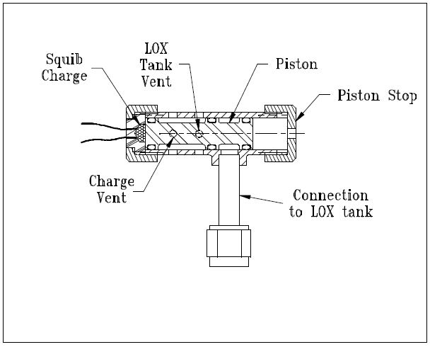
A second pyro valve is used on the Condor system as shown in Figure 5. This valve is used to vent the LOX tank in the event of a failure to open the fire valve to the engine.
FIGURE 5: Emergency vent valve for LOX tank, Condor rocket
When the propellant tanks are pressurized by the helium pyro valve, the LOX tank auto vent valve (shown in Figure 6) closes. If the engine is not fired after a reasonable amount of time, the LOX will warm up, building pressure until something gives (probably the LOX tank). The pyro valve shown in Figure 5 is used as the emergency tank vent if the engine cannot be fired. The valve body is stainless steel with a stainless tube stub welded on for connection to the LOX tank. This valve has been tested to 800 psi with helium and works fine. In this case, some ‘nicking’ of the O-rings can be tolerated because the O-rings are not required to seal after the valve is fired. The ports in the bore are still rounded, however, to prevent the O-rings from getting nicked or pinched during assembly of the valve.
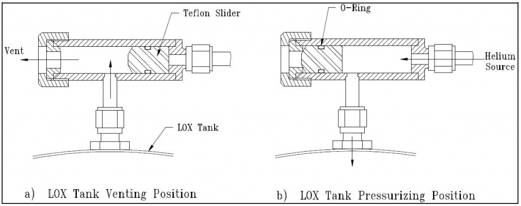
Even though it is not a pyro valve, I have shown the LOX auto-vent valve in Figure 6 because this design has proven to be very useful for venting cryogenic propellant tanks without requiring a separately actuated valve or control circuit. The valve uses a Teflon slider that is kept in the vent position as shown in Figure 6a.
This allows the tank to vent to the atmosphere, keeping the propellant at its normal boiling point. When the helium system is activated, the pressurant pushes the slider closed against the vent port, sealing off the LOX tank, as shown in Figure 6b. An O-ring is used around the slider to give it a friction fit so the aspiration of the LOX tank does not “suck” the slider to the closed position. This problem happened to David Crisalli (fellow RRS member) when he scaled this design up for use on his 1000 lbf rocket system. I have used this design on the LOX tank of my XLR-50 rocket, which used a 1/4-inch diameter slider, and on the Condor LOX tank, which uses a 1/2 inch slider. In both cases the vent valve worked perfectly.
FIGURE 6: Automatic LOX tank vent valve
The main fire valve on the Condor rocket is a pair of ball valves that are chained together to a single lever so that both the fuel and oxidizer can be actuated simultaneously for smooth engine startup. For static testing of the rocket, I will use a double-acting air cylinder to actuate the valves. For flight, however, I plan to use a pin that is removed by an explosive squib to hold the valve in the closed position. When the squib is ignited, the pin is pulled by the action of the charge on a piston, allowing the valves to be pulled to the open position by a spring. This method may not be very elegant, but it is simple, light, and packages well on the vehicle. David Crisalli has successfully employed this technique on his large rocket.
That covers the extent of the pyro valves I have built or plan to build so far. In the next newsletter, I will present the design and flight of the small hypergolic propellant rocket that used the valve shown in Figure 2.