Tank Blowdown Math

by Prof. Dean R. Wheeler, Brigham Young University


EDITOR’S NOTE

This posting is reprinted from the original article written March 13, 2019 with permission from the author. This article was intended for chemical engineering students to size relief valves for pressure vessels, but it applies well to amateur liquid rocketry as many use a pressure fed system to deliver propellants to the engine.

The PDF of this white paper can be found below.

https://www.et.byu.edu/~wheeler/Tank_Blowdown_Math.pdf

The RRS has several members engaged with liquid rocket projects. An important part of analyzing the performance of those systems is the pressurization system that drives the propellant into the engine. The tank blowdown problem is useful to designing the system and estimating performance. This derivation goes through the thermodynamics of the general tank blowdown problem and should be a useful starting point for a pressure-fed liquid rocket project.


INTRODUCTION

This document provides a mathematical model for computing the rate of expelling gas through a small orifice or nozzle attached to a tank. Furthermore, two models are described for how fast the tank will depressurize. Related material on compressible flow can be found in fluid mechanics and thermodynamics textbooks and web pages.

Figure 1 shows the tank and associated nozzle. The narrowest diameter of the flow path in the orifice or nozzle is known as the throat region. The tank and throat regions are described with their own sets of equations.

Provided the tank is large and the throat is small, it will take many seconds to empty the tank and gas velocities in the main part of the tank will be much smaller than the speed of sound. This means that gas pressure, temperature, and density in the tank will be spatially uniform, though they will be changing in time. Thus, we describe the tank using a transient mass balance. One can compare this to a model in heat transfer known as lumped capacitance.

In the nozzle region however, gas velocity is large and there are large spatial variations in the gas properties. In addition, there is relatively little gas contained in the nozzle region. Thus, flowrate in the nozzle adjusts rapidly to match current conditions in the tank, making it seem as if the nozzle is operating at steady state. This approximation for the nozzle is known as quasi-steady state.

Figure 1: Schematic of a task with nozzle or orifice, allowing gas to exit. Italicized are variables that pertain to twokey regions. During blowdown every variable depends on time,

EQUATIONS OF STATE

The P, T, and rho variables in Figure 1 denote absolute pressure, absolute temperature, and density in the tank or the narrowest part of the nozzle or throat (denoted by an asterisk,*, subscript), respectively. Note that if tank pressure is given experimentally as a gauge quantity, it must be converted to absolute to be used in the equations below.

The first relationship between gas variables is given by an equation of state. The ideal gas law is a fairly accurate representation for air when pressure is less than around 10 atmospheres or 150 psia. It states that:

Figure 1: The ideal gas equation

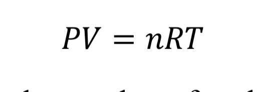
where “V” is the volume of the gas, “n” is the number of moles, and “R” is the universal gas constant (8.31446 J/mol/K). With the introduction of the molecular weight, M (effectively 0.028964 kg/mol/K for air), and the substitution that density is mass over volume, rho = n M / V, the ideal gas law is changed to

Equation 2: Density calculated from the ideal gas equation

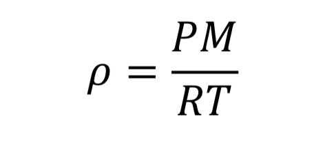
This equation could be applied separately to the tank variables or to the thrust variables.

TEMPERATURE AND PRESSURE DURING EXPANSION

The second important relationship comes from figuring out what happens when gas in the tank or nozzle expands. When a gas expands, its internal energy is used to perform work on the surroundings, and the gas therefore tends to cool off. If the gas expands slowly, there is time for itmto absorb hest from its warmer surroundings and the expansion is essentially isothermal, meaning the temperature stays at its initial value or that of the surroundings.

On the other hand, if a gas expands quickly its temperature will drop dramatically. This is called adiabatic expansion, where adiabatic means no noticeable heat transfer from the surroundings (i.e. the walls of the tank). In adiabatic expansion, the pressure drops more rapidly than it would for an isothermal (slow) expansion. Adiabatic expansion could haolen inside the tank if it is emptying rapidly, but this depends on the relative sizes of thr tank and nozzle. On the other hand, adiabatic expansion certainly occurs when a gas moves from the tank through the nozzle region. In other words, here the gas is moving quickly and therefore expanding quickly.

The thermodynamic relationships for pressure and temperature for reversible adiabatic expansion of a constant heat capacity ideal gas are:

Equation 3A: Adiabatic pressure and density relationship
Equation 4A: Adiabatic temperature and density relationship

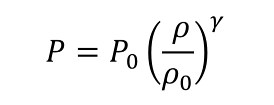
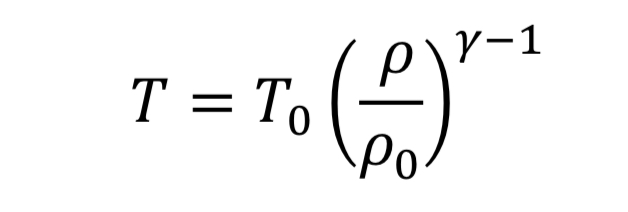
where the subscript, “o” indicates the initial state of the gas before the expansion started. This means if we know how the density is changing from an initial state to some later state, we can compute P and T as well. In the case of the nozzle, we apply the above equations as the gas travels between the tank and the throat. In the case, they become

Equation 3B: Adiabatic pressure and density relationship between tank and throat regions
Equation 4B: Adiabatic temperature and density relationship between tank and throat regions

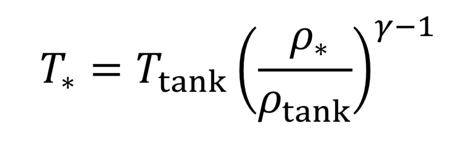
The parameter, “gamma” , is the dimensionless ratio of specific heats ( gamma =. Cp / Cv ), and by statistical theory of gases, gamma = 7/5 = 1.4, for low temperature diatomic molecules, nitrogen (N2) and oxygen (O2) and so that value is used here.

CHOKED FLOW

Next, we need to determine the gas density in the nozzle when the tank is at a specified conditions. Recall that that the nozzle is treated as if it instantaneously responds to whatever state the tank is in. A fuller discussion of the nozzle flow equations can be found in other sources like textbooks that cover ideal compressible flow in nozzles.

Choked flow means that the flow is exactly at the speed of sound in the throat region. A higher speed cannot be achieved in the throat, regardless of upstream or downstream conditions. Thus, choked flow acts to limit how much gas flow can pass through a given size orifice, This is the reason why pressure relief valves on tanks must be properly sized to accommodate sufficient flow.

Choked flow happens for a large pressure drop across the nozzle or orifice, specifically if the upstream tank pressure meets the following condition relative to atmospheric pressure downstream from the nozzle:

Equation 5: Choked flow condition

Equation 5 is the origin of the rule of thumb or approximation that choked flow occurs for upstream pressure that is more than twice the value of downstream pressure (absolute). If the tank pressure drops below this limit, the speed of gas in the throat is subsonic, and less gas will flow than in the choked flow regime. The solution to subsonic flow in the nozzle is complicated and is less important to know because it is at the end of the tank’s discharge when pressure is low, and so will be neglected here.

The solution to choked flow in the throat region follows a simple relationship, derived from energy and mass balances:

Equation 6: Throat to tank density ratio

This can be substituted from Equation 3B and 4B to determine pressure and temperature in the throat in terms of tank conditions.

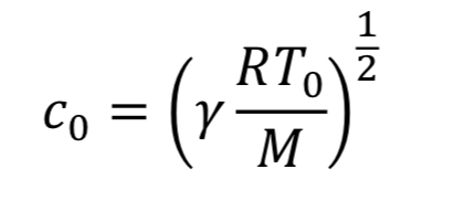
For choked flow the throat velocity is exactly the speed of sound, which is what makes it easier to analyze. For ideal gases, speed of sound, c, is determined solely by temperature. Thus, we can relate throat velocity to throat temperature, and in turn to tank temperature:

Equation 7: Speed of sound at the throat

For example, if T_tank = 294 Kelvins, then c_o = 314 m/sec for air.

MASS FLOW RATE

Now we can determine the mass flow rate, “m_dot”, through the nozzle or orifice. This comes from the following standard relationship, applied at the throat, because that is where conditions are known:

Equation 8: Mass flow,rate at the throat

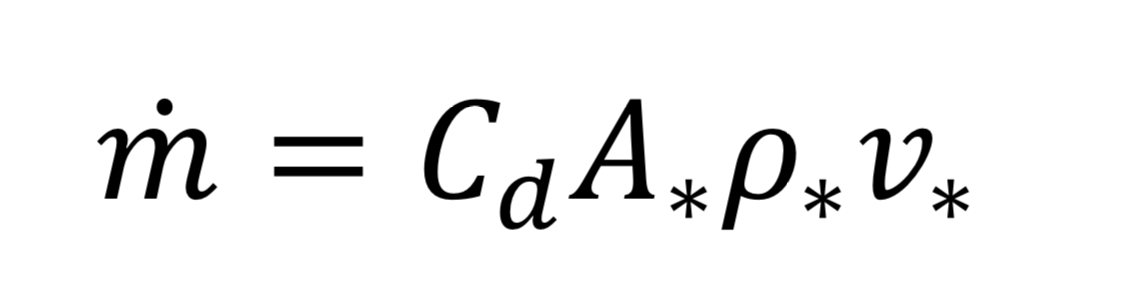
where “A_*” is the throat cross-sectional area given by

Equation 9: Area of a circle

and where “d_*” is throat diameter.

Dimensionless parameter, Cd, in Equation 8 is the discharge coefficient, accounting for friction between fluid and walls and a phenomenon known as vena contracta. In essence, Cd, is needed in Equation 8 because the effective area for fluid at speed, v_o, is somewhat smaller than actual throat area. Cd would be equal to 1.0 for a perfect (frictionless or thermodynamically reversible) nozzle: in practice for a smoothly tapering nozzle it might be as high as 0.98, while for a sharp-edged orifice it might be as low as 0.60. Anything that causes separation of flow from the nozzle wall or increases frictional contact will decrease Cd.

Making the appropriate substitutions into Equation 8 leads to an equation for mass flow in terms of readily determined quantities:

Equation 10: Mass flow rate in terms of readily determined quantities

Frequently in industrial situations, mass flow rates are expressed instead as volumetric flow rates corresponding to a gas at a standard temperature and pressure (even though the gas is not actually at that temperature and pressure). For instance, a mass flow meter used for gases may express mass flow as standard liters per minute (SLPM) or standard cubic feet per minute (SCFM). In other words, even though m_dot (mass flow) is the key value being measured, it is expressed as

Equation 11: Standard volumetric flow and mass flow rate

which requires knowing what rho_std value is programmed by the manufacturer into the flow meter. This can be determined from the ideal gas law, given specified P_std and T_std values. As an example, the American manufacturer, Omega, assumes a standard temperature “T_std” of 70 degrees Fahrenheit (294.26 Kelvins) and a standard pressure “P_std” of 1 atmosphere which equals 14.696 psia (101,325 Pscals) thus by the ideal gas law, the standard density “rho_std” would equal 1.2 kg/m3 for air (molecular weight 28.97 g/mole).

Combining Equations 10 and 11 and the ideal gas law leads to

Equation 12: Combining Equations 10 and 11 for standard volumetric flow rate

where “c_std” is the speed of sound at the standard temperature:

Equation 13: Standard volumetric rate and mass flow rate relationship

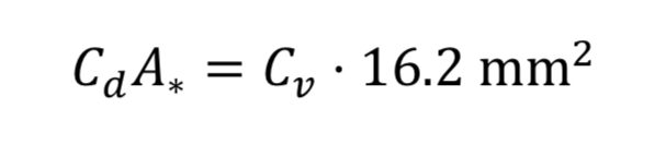
Makers of valves and orifices may provide an experimentally determined size parameter known as flow coefficient, Cv. For gases this dimensionless parameter can be converted to Cd*A_* by

Equation 14: Discharge area relationship4 to valve coefficient (metric units)

The key design principles resulting from the above analysis are, provided tank pressure is large enough to generate choked flow, that (1) mass flow rate of a gas through an orifice is proportional to throat area and tank pressure and (2) flow rate does not depend on downstream pressure.

TWO MODELS OF TANK BLOWDOWN

Equation 10 gives the rate of mass loss from a tank at a given gas density and temperature. To determine how long it will take to depressurize the tank, we must do a transient mass balance on the tank. The ordinary differential equation for this is:

Equation 15: Change of mass in time

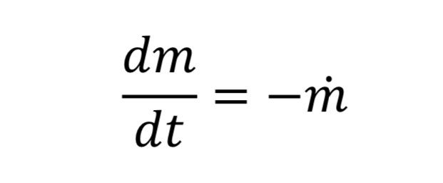
where “m_dot” comes from Equation 10 and “m” is the mass of gas in the tank. This in turn is:

Equation 16: Mass in the tank

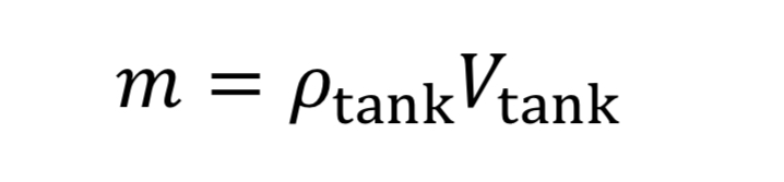
where V_tank is the fixed tank volume. With these substitutions we get for the governing equation

Equation 17: Mass flow rate from the tank

To make things more manageable, let us create a discharge time constant called “tau”

Equation 18: Time constant for blowdown of a tank

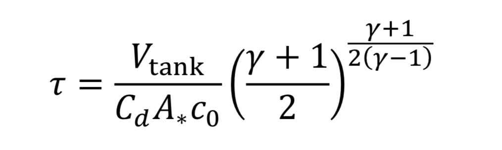
where “c_o” is the speed of sound at the initial temperature “T_o” (i.e. at the beginning of blowdown)

Equation 19: Speed of sound at initial conditions

With this new time constant, Equation 17 becomes:

Equation 20: Mass flow rate change in the tank

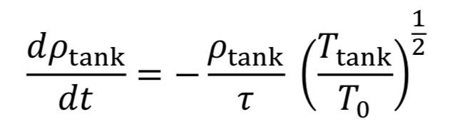
The last thing to do before solving this equation is figure out what to do with T_tank. We have two options:

ISOTHERMAL TANK ASSUMPTIONS

Assume gas temperature in the tank does not change in time, based on blowdown taking a long time so that heat can be readily absorbed from the walls. Thus, T_tank = T_o. This leads to Equation 20 becoming

Equation 21: Tank density change in time

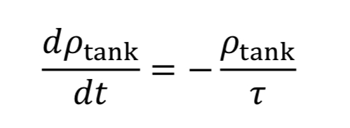
which can be separated and integrated to give the solution

Equation 22: Tank density as a function of initial conditions

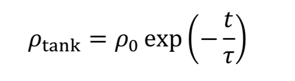
where “rho_o” is initial density in the tank. We then convert densities to pressure using the ideal gas equation.

Equation 23: Tank pressure as a function of initial conditions

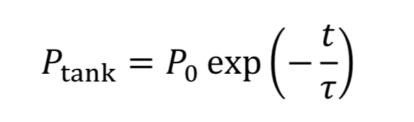
The equation tells us how tank pressure varies with time, for an isothermal tank and choked exit flow.

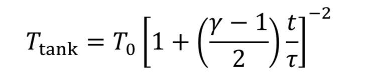
ADIABATIC TANK ASSUMPTIONS

Assume the gas cools as it expands in the tank, due to no heat transfer from the walls, based on the blowdown taking a short time to complete. Thus, T_tank is given by Equation 4A. This leads to Equation 20 becoming

Equation 24: Mass flow rate from the tank

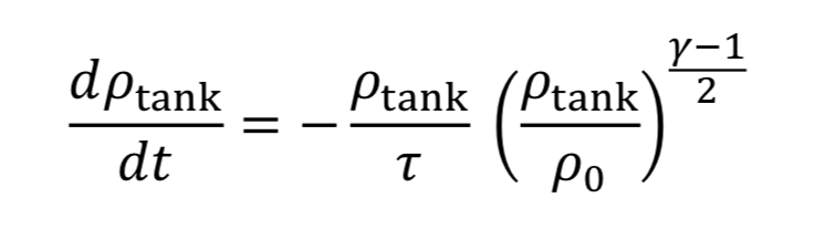
which can be separated and integrated to give a solution.

Equation 25: Density of the tank as a function of time

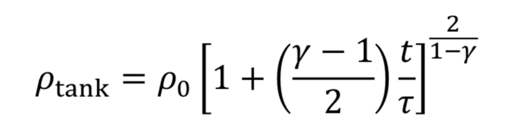
We then convert densities to pressures using Equation 3A for adiabatic expansion.

Equation 26: Tank pressure as a function of time

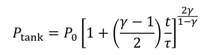
This equation tells us how tank pressure varies with time, for an adiabatic tank and choked exit flow. The tank temperature can likewise be predicted from Equation 4A.

Equation 27: Tank temperature as a finction of time

COMPARISON OF THE TWO MODEL ASSUMPTIONS

The isothermal and adiabatic models of tank blowdown can be considered two extremes, with the correct answer (i.e., with the true amount of heat transfer) lying somewhere in between them. Figure 2 shows an example of the respective blowdown curves (Equation 23 and 26). As noted previously, adiabatic tank conditions lead to more rapid pressure loss than do isothermal conditions.

The curves predict that the tank will have lost 80% of its original pressure at a time in the range of 1.3*tau < t < 1.6*tau. This shows the value of evaluating the variable, tau, to get an approximation of the time it takes to depressurize the tank.

Figure 2: Comparison of isothermal and adiabatic blowdown curves.

Burst discs in liquid rocketry

by Dave Nordling, Secretary, Reaction Research Society


I was recently asked for advice on the installation of a burst disk in a university liquid rocket project. As any pressure relief device is an important subject to consider carefully, I wanted to present a summary of my thoughts to our broader readership.

The Reaction Research Society (RRS) is happy to offer advice, but my first recommendation to any university team would be to talk with your university professors, professional advisers and mentors that are involved with your project. A burst disk is an important component and its function can be critical for safety and preserving your vehicle in any over-pressurization scenario. The subject of your rocket system pressurization, venting and relief devices is extremely important to study well and thoroughly understand before proceeding with any component selection or testing.  Your university is the best place to start.

For those who are doing a liquid rocket project outside of a university program, I would also recommend to consult with experts and reputable manufacturers and distributors of pressure relief devices including burst disks.

Burst discs (the spelling “disk” or “disc” is interchangeable) are one simple form of a pressure relief device or valve that is designed to prevent over-pressurization of a pressure vessel and potential catastrophe.  Burst disks are also sometimes called “rupture disks” which clearly describe their function.

https://en.wikipedia.org/wiki/Rupture_disc

In liquid rocket system designs, burst disks are often placed not only at the pressurant bottle to protect the higher pressure part of the system, but also at the lower pressure end of the regulator which protects the propellant tanks being pressurized. In the event of pressure regulator failure, the burst disk can protect the propellant tank.

Burst disks are usually in the form of a dead-ended pressure fitting that is adapted to directly connect into the pressure vessel either directly into the pressure vessel volume boundary itself or by a tube connection that is also directly connected into the pressure vessel volume boundary. These fittings have a frangible or breakable membrane that is designed to fail when the pressure reaches a specific design point.

An illustration of the burst disk fitting concept

A burst disk is a “one-time use” device and can not be reset after they have “actuated”. As a pressure relief device, the burst disk is often chosen for its compact size and simplicity. They are in common usage in many industries and can fulfill their relief function very well if they are sized and located properly.

They must be securely and directly connected into the volume of the pressure vessel and have no valves or other hardware which would isolate, block, impinge or constrain the relief function in any way. The American Society of Mechanical Engineers (ASME) Boiler and Pressure Vessel (B&PV) code does have some general advice on this subject and this is a good place to start your study.

These devices are simple to understand but fairly complex to size properly. Beyond the design of the burst disk, you must also consider where these devices will physically fit on your vehicle, where are they located and what is the environment doing around your relief device

The burst disk body and membrane can be subject to corrosion or physical damage that could reduce it’s effective bursting pressure. It’s important to consider the material compatibility of all body, seals and membrane materials that are exposed or “wetted” to the gases inside. Also, its important to avoid getting gouges, nicks or marks on the membrane that would form stress concentrations and weaken the membrane. Even when being cautious, don’t leave your burst disk covered when it needs to be ready to perform. Careful handling is good advice at all points in the project.

There are three things to consider when locating and installing a burst disk:
(1) relief (set) pressure, (2) minimum flow rate required, (3) where is your burst disk pointed?

(1) Set pressure of the relief device

Any relief device must be set to actuate (or in the case of a burst disk, to rupture) at a pressure above all of your nominal conditions, but also adequately below any and all failure modes.  In some pressure vessel or relief device codes, there are rules of thumb about the set pressure must be a specific percentage (%) above the maximum expected operating pressure (MEOP) or maximum allowable working pressure (MAWP). The thorough examination of all operating conditions and hardware limitations is essential of finding the right set pressure for the relief device. 

ASME also has codes for sizing relief valves in process piping, but the rocket industry doesn’t have a particular specification. The aerospace industry does often draft their own specifications and requirements which follow good industrial practices and always include careful design and testing as part of proving the designs to be sufficient.

Another consideration beyond the static pressure in your pressure vessel is the temperature environment of the gases inside. Beyond the fact that higher temperatures from a thermodynamic standpoint create higher pressures, a burst disk relies on the material strength of the membrane and the yield and ultimate strength can weaken under higher temperatures. Some materials (examples are low quality steels) can also become weaker under cold temperatures. Always consider the full range of temperature environments in every application. It’s important to size each burst disk individually and resist the temptation to assume that one device will suit all environments.

There’s a big tolerance on a burst disk set pressure, so be aware of that imprecision. Burst disks are compact but getting a membrane to burst at an exact pressure is not really practical and thus these devices are not very precise.  Ask the manufacturer about the expected tolerance on any relief device. It’s also wise to test a few of these devices to measure the actual burst pressure. Make sure you are recording data because failure happens suddenly and you are unlikely to visually see the last pressure reading before burst. If you blink, you can miss the most important data point. Therefore, use a data acquisition system when testing your pressure relief devices.

(2) Minimum flow rate required

Any pressure relief device when activated must be able to drop pressure fast enough to avoid over-pressurizing and failing the pressure vessel. This is a less commonly evaluated situation but its equally important to recognize any scenarios where the transient pressure rise would challenge the relief flow rate needed to keep the pressure below a safe level at all times. Steam pressure systems have this problem and so do cryogenic vessels.  Most designers just choose a fitting similar in size to the lines being used, but this isn’t always accurate. 

Relief devices are nearly always sized relative to their flow rate afforded.  This is sometimes called the “capacity” of the relief valve or burst disk. You’ll need to know your gas and upstream conditions. With this, you’ll need to know the open area when the valve is opened and make this is the smallest restriction in the entire flow path. The open area can be expressed as either the discharge area (Cd A) or the valve coefficient “Cv” value. With each device in each specific location, you must select a burst disk capable of venting enough flow to cover the whole range of expected conditions. This is crucial to finding the right burst disk or relief valve. A device that does not have a large enough capacity will not protect your fluid system.

Another consideration for your relief device is if you have any flow path that is smaller than the area of your relief device. One example of poor design is having your pressure relief device located at the end of a long skinny tube. Even if the open area of the tubing is larger than the pressure relief valve opening, the length of the line can accumulate enough flow friction in the tubing that can unintentionally add up enough pressure drop to pose a significant restriction to your relief flow. This is to say nothing of someone accidentally denting or kinking the tubing which would create a severe blockage of the relief flow. It’s always smart to have your pressure relief device very closely coupled to the pressure vessel volume that you are protecting. This means keeping the distance as short as possible. Always know all of your flow path areas and line lengths!

Another classic mistake in fluid system design is putting a valve or any other restriction device in-between the pressure boundary volume and the pressure relief device that is protecting it. Careful consideration of all valve placements and their positions in all operating modes and under all possible operating scenarios. Put simply: “Do NOT EVER create a situation where the pressure relief device can be isolated or impeded in its operation at any time for any reason, even temporarily. Some piping codes absolutely forbid this. Careful peer-review of your pressure and instrument diagrams (P&ID’s) must look for this situation and avoid it. More than reviewing the paper schematics, one should physically trace all flow paths to be sure the builder hasn’t made such a mistake. The physical hardware must always match the P&ID.

(3) Watch where your burst disk is pointed! 

When your burst disk goes off, any foreign object debris (FOD) near the discharging outlet can be thrown out at high speed causing injury or damage to nearby hardware and structures. Even without particulates or FOD, the impinging high-speed sonic jet of gas is very dangerous.  No one should be standing near a fluid system while any part of it is pressurized anyway, but you should always consider what might happen when your burst disk goes off. You won’t always know when the device will go off. Be prepared at all times.

Make sure all hardware is also secure enough to take the sudden thrust from the burst disk relieving itself. This can be a sudden and powerful force that breaks hardware or knocks things over. The rocket thrust equation also applies in this case. To calculate this thrust value, you do this in two parts: (1) You consider the choked flow pressure differential multiplied by the discharge area and (2) add in the product of the mass flow rate of the gas escaping multiplied by the sonic velocity of the upstream gas conditions.

Calculation of the thrust load from a discharging relief device such as a burst disk

As a design note, for nearly all gases, if the upstream pressure is more than double that of the downstream pressure, the flow velocity through any flow path restriction(s) or “orifice area” is sonic or at the speed of sound as computed by the upstream gas pressure and temperature conditions. This is called “choked” flow.

One potential fix to the jet thrust problem out of relief device is to divert and diffuse the discharging outlet flow in opposing or evenly distributed directions as long as the combined discharge flow areas are sufficiently large and balanced.

An illustration of a burst disk device with balanced venting

Another consideration to be made with a burst disk or pressure relief device is to consider the downstream environment where your burst disk is discharging.

Is the relieving gas or gas mixture going to create a flammable or toxic environment? If so, you need to consider how and where you are diverting the hazardous gases being relieved. Some burst disk fittings have threaded ends on both ends which allows the discharging flow to be routed to a safe location, if this is a necessary feature.

Screw-type burst disk fittings made by Zook in three basic types

Are you creating a dangerous environment (reduced oxygen) within a confined space? The subject of confined space safety is very important and worthy of a separate article in itself. Most testing will be done outdoors and in a very well ventilated environment, but the rocket business is full of horror stories of people who have become injured or asphyxiated simply from improper consideration of confined space safety.

A less often considered scenario is whether the space where the burst disk or relief valve is discharging into is fully open to the environment or not. It is possible to overly restrict or “back up” a burst disk or relief valve if the interstage volume in your rocket isn’t very large or isn’t adequately vented to the outside. Sometimes your discharge space simply isn’t big enough. It is very important to know your vehicle hardware geometry very well, measure your volumes and consider all flow areas out of all assemblies.

Find a reputable burst disk manufacturer and distributor

There are a few reputable manufacturers of burst disks. Fike is one that comes to mind, but they tend to be for very large piping sizes used in facility plants. Fike has been providing reliable products for many years to many industries including oil/gas and the aerospace industry. Swagelok has access to a lot of fluid component manufacturers which may be more suitable.

Zook is another manufacturer of burst disk fittings. These in-line devices come as a holder fitting and replaceable disk. The screw-type fittings are two-piece assemblies and have standard pipe thread ends. The disks come in a range of nominal set pressures.

Screw-type burst disk fittings by Zook

zookdisk.com

There are certainly other manufacturers and all of them should be able to provide you with good advice or transfer you to a distributor company to help you with selecting an appropriate device. Before you call or email, you must have already taken the time to understand your pressure environment, capacity and design requirements first. A good component distributor is one that is willing to work with you to find the right part for your application and educate you in making the best choice. Literature is easy to find online and always consider more than one manufacturer to get a good price.

A few last words of caution

Burst disk devices can be manufactured from scratch and other amateur rocketry hobbyists have attempted to do so. This is not a good idea. There are a lot of considerations to make in building a reliable burst disk from scratch not to mention the time and materials to adequately prove the design. To make a burst disk from scratch would become every bit as expensive as simply going to a reputable manufacturer and using their product.

As much as your group may want to save money, pressure relief devices are a critical part of your fluid system to which lives may be at stake.  Don’t be cheap. Find a quality manufacturer, select the right product and test them.  Ebay is not the place to find quality products.


If anyone has anything to add to this subject, please contact the RRS secretary or the RRS director of research.

secretary@rrs.org

research@rrs.org